Lab 3: Time of Flight Sensors
Prelab
The goal of this lab is to set up two VL53L1X time-of-flight sensors and get them ready to be mounted on the RC car for future labs. The sensors work by emitting infrared light and measuring how long it takes to bounce back, which gives a distance estimate.
I2C Address
The VL53L1X default I2C address is 0x52 per the datasheet, but the Arduino Wire library uses 7-bit addressing, so it shows up as 0x29 (0x52 » 1). Both sensors share this hardwired address, so they can’t be used simultaneously without some fix.
Handling Two Sensors on the Same Bus
There are two common approaches. One is to toggle XSHUT at runtime and keep one sensor off while reading the other, but that means you can only ever read one sensor at a time. The other is to remap one sensor’s address at startup: bring up sensor 1 first, move it to 0x30, then bring up sensor 2 at 0x29. Both sensors live on the bus with no conflicts.
I went with address remapping. The catch is that you need XSHUT control on both sensors, not just one. Without it, a hot-restart leaves sensor 1 sitting at 0x30 from the previous run, and begin() fails because it scans at 0x29. I soldered XSHUT wires for both sensors: sensor 1 XSHUT → A1 (GPIO 1), sensor 2 XSHUT → A0 (GPIO 0). Both pins go LOW in setup() to hardware-reset both sensors, then they’re released one at a time in init_tof_sensors().
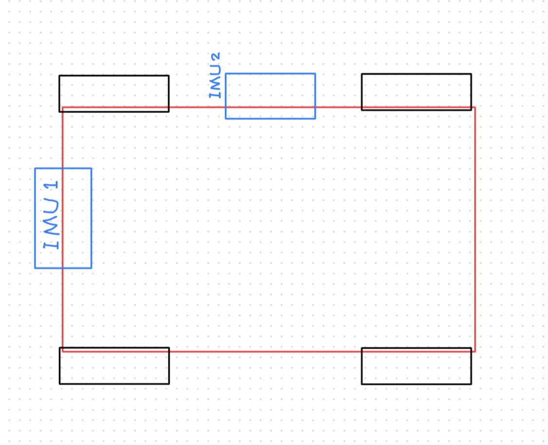
Sensor Placement
The front-facing sensor is the primary one since the robot mostly drives forward. The second is mounted on the right side to detect walls during mapping in later labs.
Scenarios where the robot will miss obstacles:
- Objects behind the robot
- Objects on the left side
- Very thin objects that the IR beam passes between
- Very dark or matte black surfaces that absorb IR
- Transparent obstacles like glass
Wiring Plan
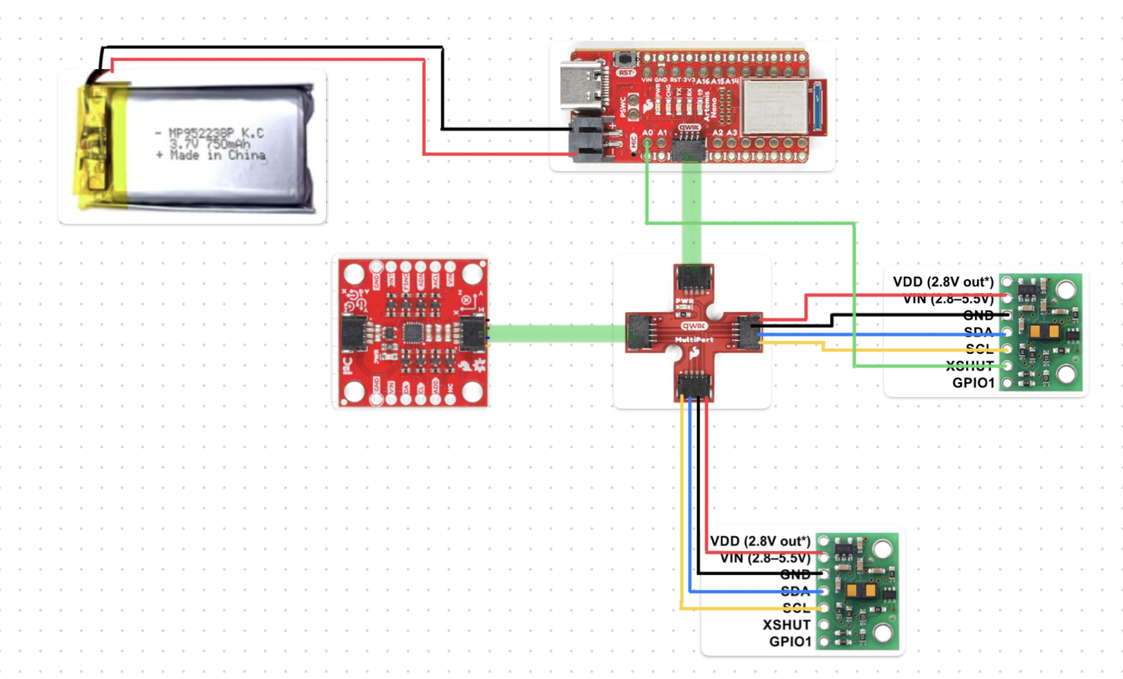
Long QWIIC cables go to the ToF sensors so they can reach their mounting spots on the car. The IMU uses a shorter cable since it stays close to the Artemis. XSHUT wires are soldered permanently to each sensor and connect via female-to-female jumper wires to A0/A1 on the Artemis.
Battery
First step was to solder the JST cable to the 650 mAh battery one wire at a time, because cutting both at once shorts the terminals. Used heat shrink to insulate each joint.
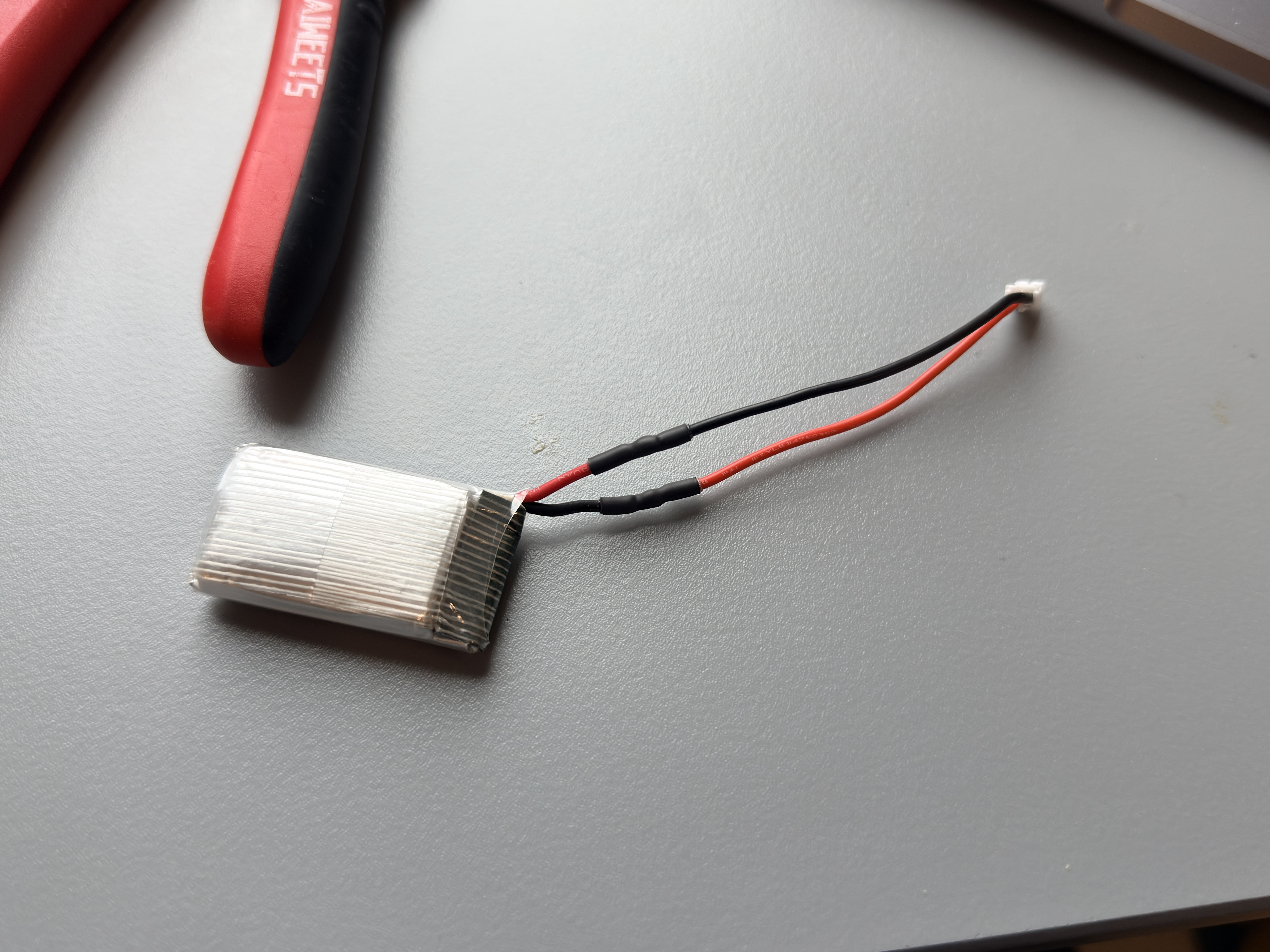
The battery wire polarity doesn’t necessarily match the color convention on the Artemis side. I got it wrong on the first try and the board started smoking. Pulled the battery fast, checked polarity with a multimeter, re-soldered correctly, and it was fine.
First ToF Sensor Setup
Installed the SparkFun VL53L1X 4m library, cut a long QWIIC cable, and soldered it to sensor 1. Blue = SDA, yellow = SCL per the datasheet.
Connected it to the QWIIC breakout board on the Artemis to verify the solder joints:
I2C Address Scan
Ran the I2C scanner example. The sensor shows up at 0x29, not 0x52. This is just a convention difference: the Arduino Wire library drops the R/W bit from the 8-bit address, so 0x52 becomes 0x29. The address is correct.
Two ToF Sensors Simultaneously
Both XSHUT wires wired up, sensor 1 to A1, sensor 2 to A0. The init sequence holds both LOW at startup, then releases them one at a time:
Arduino: init_tof_sensors()
#define SHUTDOWN_PIN_1  1   // A1 → sensor 1 XSHUT
#define SHUTDOWN_PIN    0   // A0 → sensor 2 XSHUT
#define TOF1_ADDR     0x30  // sensor 1 remapped here

void init_tof_sensors() {
    // Both XSHUT pins are already LOW from setup() — sensors in hardware reset.
    // Release sensor 1 first so it boots exclusively at 0x29.
    digitalWrite(SHUTDOWN_PIN_1, HIGH);
    delay(10);

    if (tofSensor1.begin() == 0) {
        tofSensor1.setI2CAddress(TOF1_ADDR);  // remap → 0x30
        tofSensor1.setDistanceModeLong();
        tofSensor1.startRanging();
        tof1Ready = true;
        Serial.println("ToF sensor 1 OK");
    } else {
        Serial.println("ToF sensor 1 FAILED");
    }

    // Now release sensor 2; sensor 1 is already at 0x30, no collision.
    digitalWrite(SHUTDOWN_PIN, HIGH);
    delay(10);

    if (tofSensor2.begin() == 0) {
        tofSensor2.setDistanceModeLong();
        tofSensor2.startRanging();
        tof2Ready = true;
        Serial.println("ToF sensor 2 OK");
    } else {
        Serial.println("ToF sensor 2 FAILED");
    }
}
After this, sensor 1 lives at 0x30 and sensor 2 at 0x29. Since both XSHUT pins are driven LOW every time the Artemis boots, the sensors always start from a clean reset state, so hot-restart works fine now.
Distance Mode Comparison
The VL53L1X has two main distance modes:
| Mode | Max Range | Timing Budget | Ambient Light Sensitivity |
|---|---|---|---|
| Short | ~1.3 m | ≤ 20 ms | Low |
| Long | ~4 m | ≥ 33 ms | Higher |
Short mode is more robust in bright light but tops out at 1.3 m. Long mode reaches 4 m but gets noisy past ~2 m in direct sunlight.
I’m using Long mode as the default. The lab arenas are indoors without intense ambient IR, and 4 m range is more useful than extra noise immunity. One thing I learned the hard way: you must call stopRanging() before switching modes. Calling setDistanceMode() while actively ranging corrupts internal timing registers and causes a ~130 mm systematic offset on every subsequent reading.
Characterization — Range, Accuracy, Repeatability
I collected 50 single-shot readings at 5 distances: 100, 500, 900, 1300, and 1700 mm, for both sensors in both Short and Long mode.
Later in the lab 4, I also 3D-printed ToF sensor mount to make them on robot solidly.
Sensor 1 Accuracy
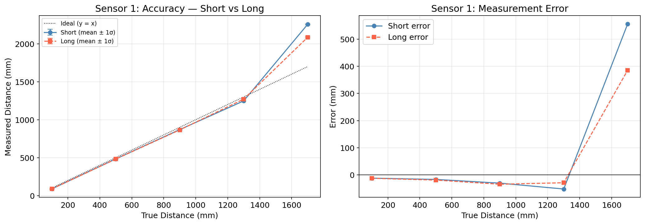
Sensor 1 reads consistently 15–30 mm below the true value in Long mode, which is a normal mounting offset from the lens cover. Short mode performs similarly within its range, but the 1700 mm readings blow up to ~2200 mm, which is well beyond Short mode’s 1.3 m limit.
Sensor 2 Accuracy
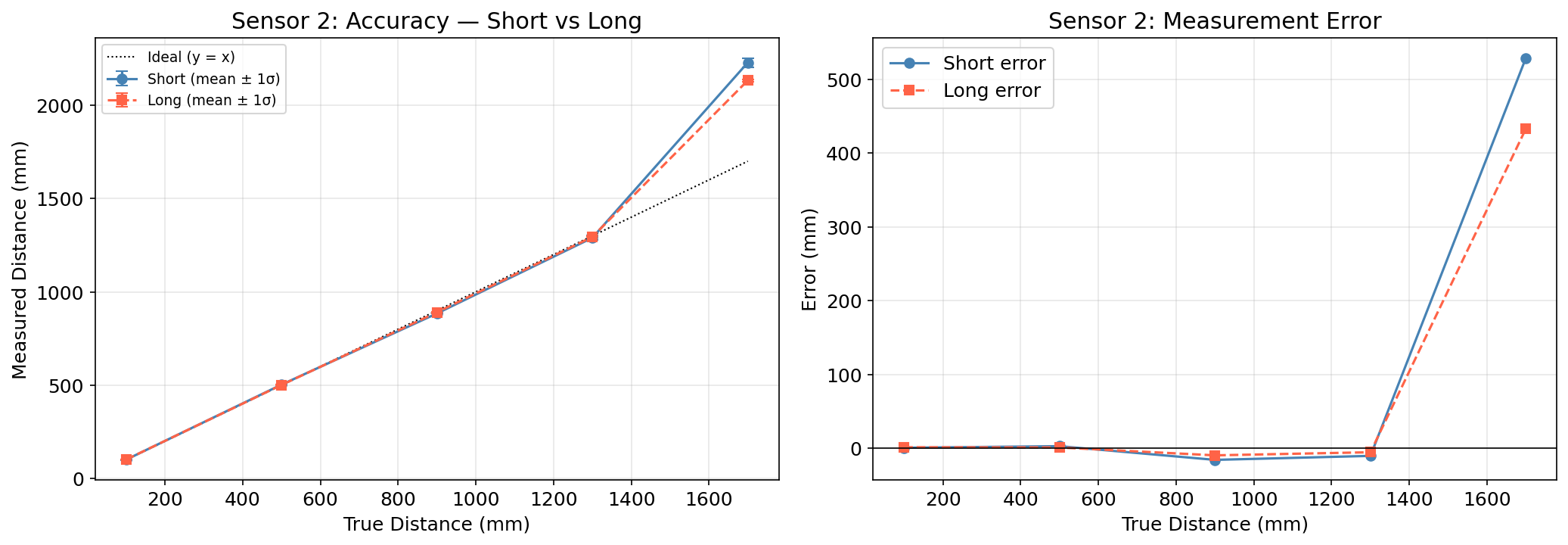
Sensor 2 is more accurate in absolute terms, with error within ±15 mm from 100–1300 mm. Both modes blow up at 1700 mm for the same reason.
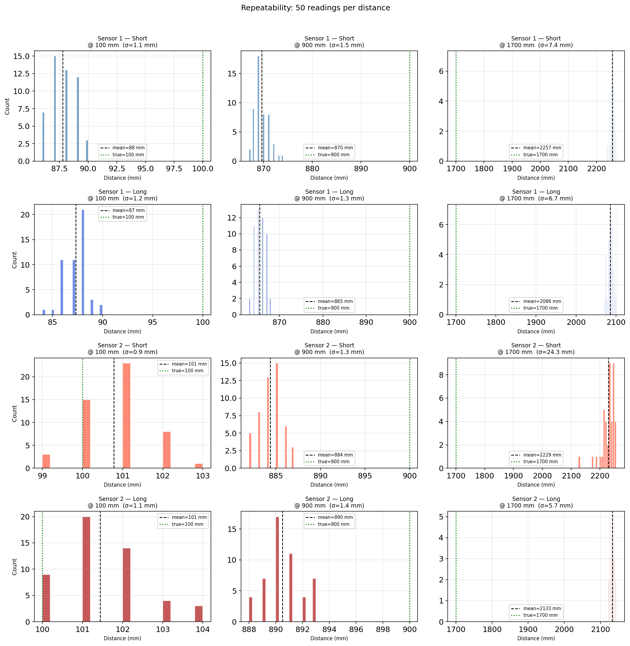
Repeatability
σ is under 2 mm for all distances up to 1300 mm. The 1700 mm histograms are widely spread or bimodal, confirming the sensor shouldn’t be relied on past its rated range.
Non-Blocking Loop Speed
The main loop can’t stall waiting for sensor data in future labs. Using checkForDataReady() lets the loop run at full speed and only processes data when it’s actually available.
Arduino: record_tof_data()
void record_tof_data() {
    if (!tof1Ready || tofArrayFull) return;
    if (!tofSensor1.checkForDataReady()) return;  // non-blocking — just skip if not ready

    tofTimeStamps[tofIndex] = millis();
    tofDist1[tofIndex] = (int16_t)tofSensor1.getDistance();
    tofSensor1.clearInterrupt();

    // Read sensor 2 opportunistically — it might not be ready every cycle
    if (tof2Ready && tofSensor2.checkForDataReady()) {
        tofDist2[tofIndex] = (int16_t)tofSensor2.getDistance();
        tofSensor2.clearInterrupt();
    } else {
        tofDist2[tofIndex] = -1;
    }

    tofIndex++;
    if (tofIndex >= MAX_TOF_SIZE) {
        tofArrayFull = true;
        collectingTOF = false;
    }
}
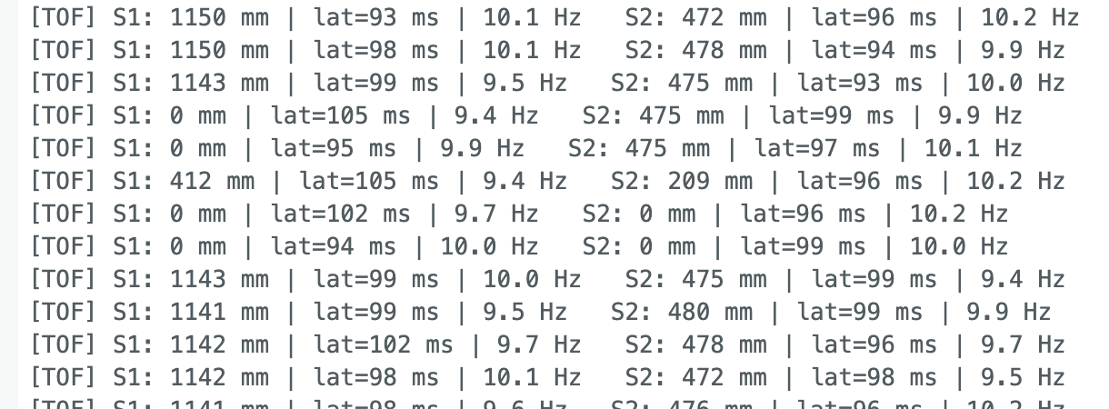
Each loop iteration takes on the order of tens of microseconds. The limiting factor is the ToF sensor ranging time: Long mode uses a 33 ms timing budget, capping the data rate at ~30 Hz theoretically and ~10 Hz in practice. The IMU runs faster since it just reads an I2C register, bounded by its ODR at ~100 Hz.
Distance vs Time
Sent START_TOF_RECORDING, moved the sensors around for ~6 seconds, then retrieved the data over BLE.
Arduino: SEND_TOF_DATA
case SEND_TOF_DATA: {
    int limit = tofArrayFull ? MAX_TOF_SIZE : tofIndex;
    for (int i = 0; i < limit; i++) {
        tx_estring_value.clear();
        tx_estring_value.append("T|");
        tx_estring_value.append((int)tofTimeStamps[i]);
        tx_estring_value.append("|");
        tx_estring_value.append((int)tofDist1[i]);
        tx_estring_value.append("|");
        tx_estring_value.append((int)tofDist2[i]);
        tx_characteristic_string.writeValue(tx_estring_value.c_str());
        delay(10);
    }
    break;
}
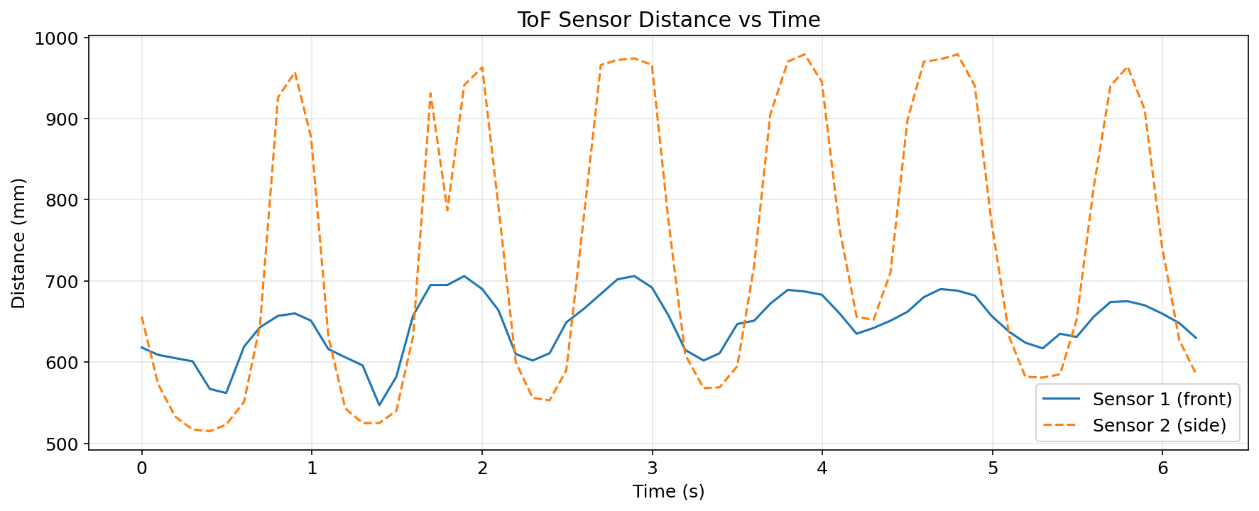
Both sensors track distance changes over time. I moved the car forward and backward.
IMU Angle vs Time
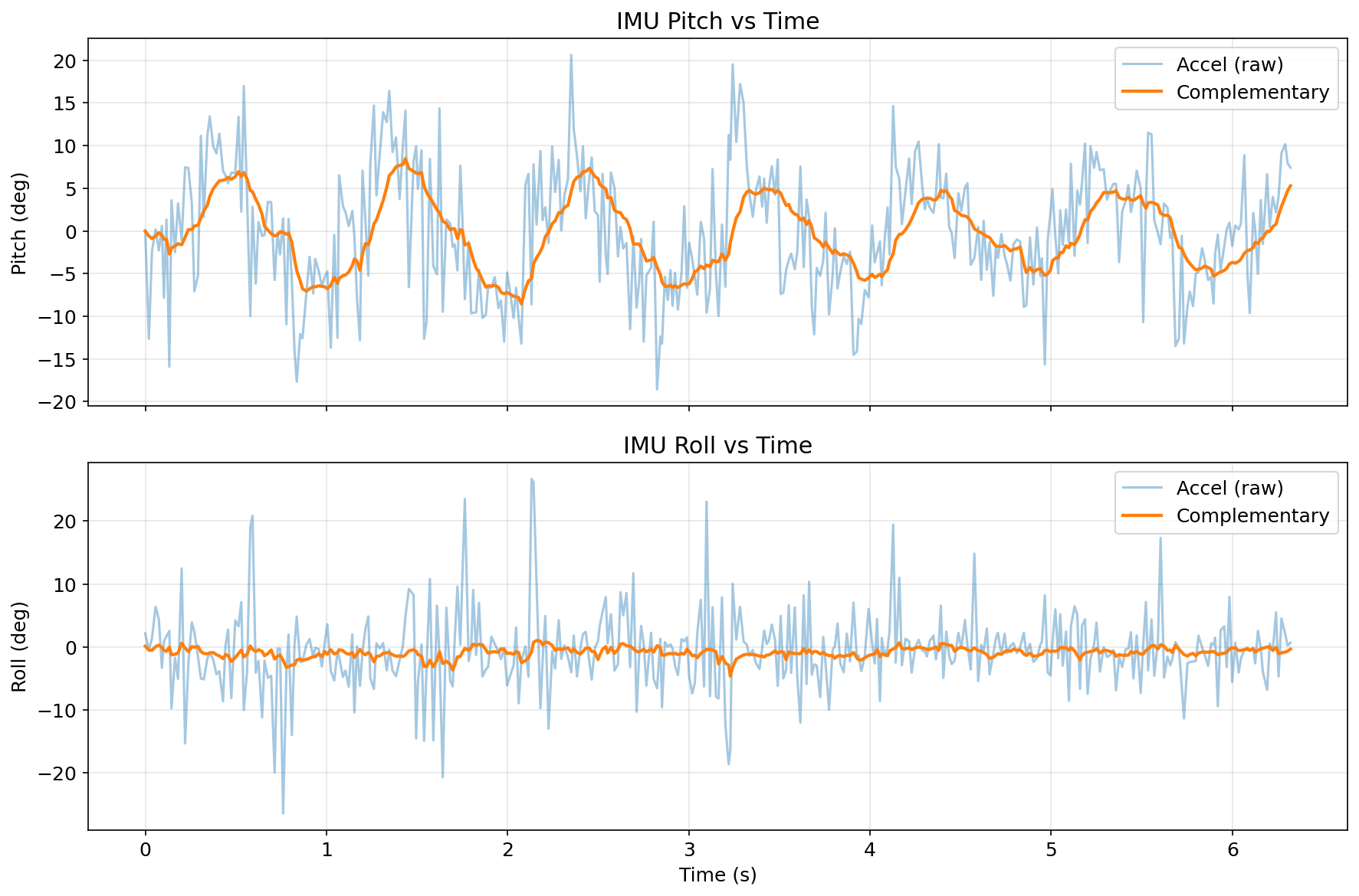
I moved the car forward and backward. Pitch and roll from the complementary filter vs raw accelerometer. The filter smooths accelerometer noise while avoiding gyroscope drift accumulation.
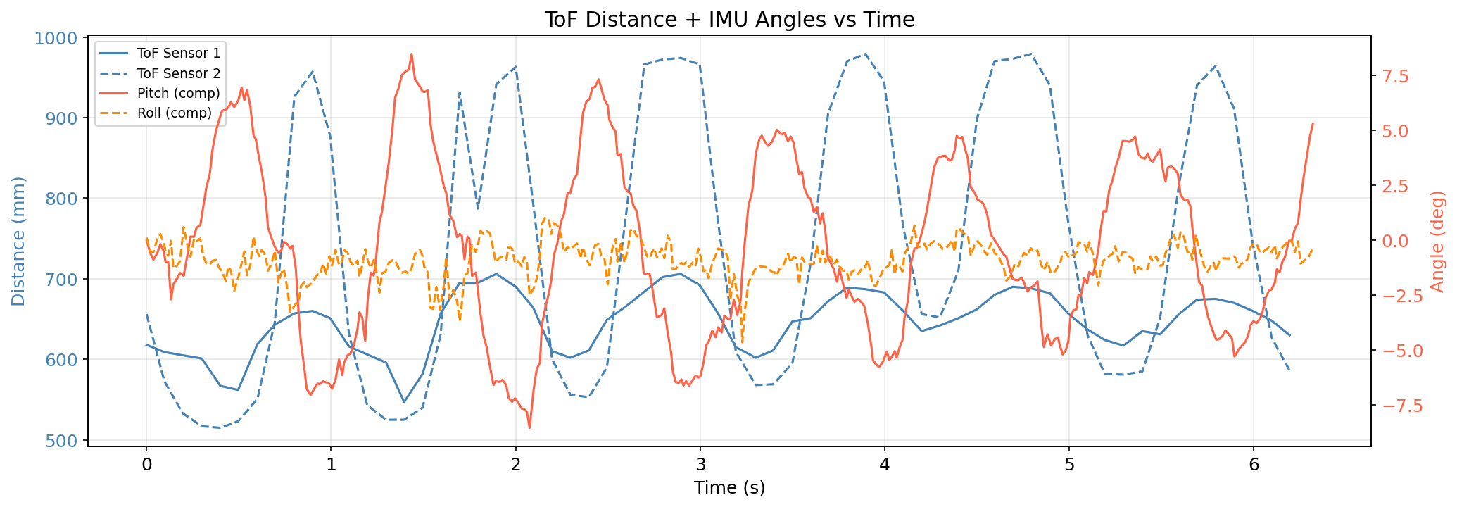
Combined ToF + IMU
Both datasets on one figure with dual y-axes, distance on the left, angle on the right. The IMU trace seems more frenquent since it samples at a higher rate (10Hz vs. 50Hz).
Meet my cat Mulberry! 🐱