Lab 4: Motors and Open Loop Control
My robot Mulberry has fully completed its great hardware assembly, and the name is in honor of my cat, Mulberry.

Prelab
Wiring Plan
For PWM output I needed pins that support analogWrite. Pins 8 and 10 are not PWM-capable on the Artemis Nano, so I ended up using A3, A14, A15 and A16. These four sit on the opposite side of the board from the USB programming port, so the port can face the edge of the chassis while the motor wires run toward the center where the motors are.
Each dual motor driver runs in parallel-coupled mode: both input channels tied together, both output channels tied together. This doubles the average current the chip can deliver without overheating, since both H-bridge halves share the load. Left motor uses pins 3 and 14, right motor uses pins 15 and 16.
Battery Separation
The motors run off an 850 mAh Li-Ion and the Artemis runs off its own 650 mAh battery. The main reason isn’t just capacity but also electrical isolation. When a motor suddenly draws a huge spike of current, the battery voltage can dip momentarily. If everything shares one battery, that dip can pull the Artemis supply below its minimum operating voltage and crash it. Separate supplies prevent that. They also let each battery be sized and charged for its actual load.
Power Supply and Oscilloscope
I started with the motor driver (VIN) on an external bench supply set to 3.7 V, matching the Li-Ion battery voltage. I started at 100 mA current limit, which wasn’t enough to drive the motor at all. I stepped it up gradually and found 300 mA was sufficient for the oscilloscope tests with the motor running freely.
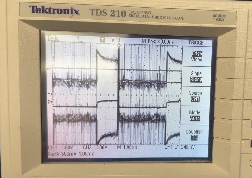
For the oscilloscope test I used a standalone sketch that cycles the motor forward and backward at a fixed PWM, with a separate version that holds a constant 30 to 256 PWM cycle for a clean waveform capture:
Arduino: motor_test.ino — forward/backward cycle
#define L_FWD  3    // Left  motor forward  (AIN1)
#define L_BWD  14   // Left  motor backward (AIN2)
#define R_FWD  16   // Right motor forward  (BIN1)
#define R_BWD  15   // Right motor backward (BIN2)

#define SPEED  150  // PWM 0–255

void motorsForward(int speed) {
    analogWrite(L_FWD, speed);  analogWrite(L_BWD, 0);
    analogWrite(R_FWD, speed);  analogWrite(R_BWD, 0);
}
void motorsBackward(int speed) {
    analogWrite(L_BWD, speed);  analogWrite(L_FWD, 0);
    analogWrite(R_BWD, speed);  analogWrite(R_FWD, 0);
}
void motorsStop() {
    analogWrite(L_FWD, 0); analogWrite(L_BWD, 0);
    analogWrite(R_FWD, 0); analogWrite(R_BWD, 0);
}

void loop() {
    motorsForward(SPEED);   delay(5000);
    motorsStop();           delay(1000);
    motorsBackward(SPEED);  delay(5000);
    motorsStop();           delay(1000);
}
Arduino: fixed 30% duty cycle for oscilloscope waveform
void loop() {
    // around 30% duty cycle — PWM value 75 out of 255
    analogWrite(L_FWD, 75);
    analogWrite(R_FWD, 75);
}
The oscilloscope shows the two PWM channels are 180° out of phase. That makes sense: the two motors are mounted facing opposite directions in the chassis, so driving them both “forward” electrically means one spins clockwise and the other counterclockwise.
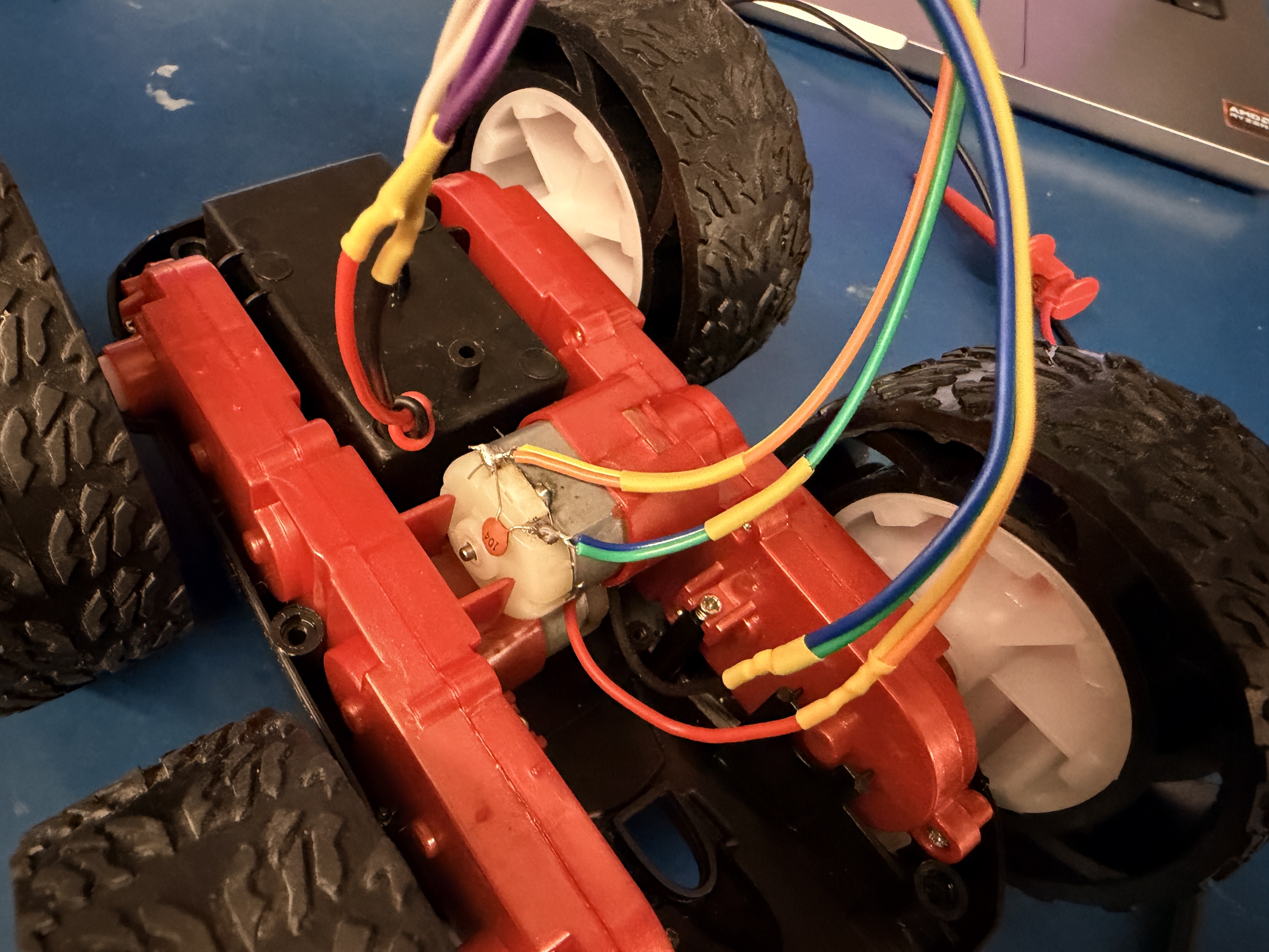
Assembly
I disassembled the stock car, cut the original PCB out, and started routing wires for the motor drivers. Below is the progression from initial motor wire connections through the final installation.
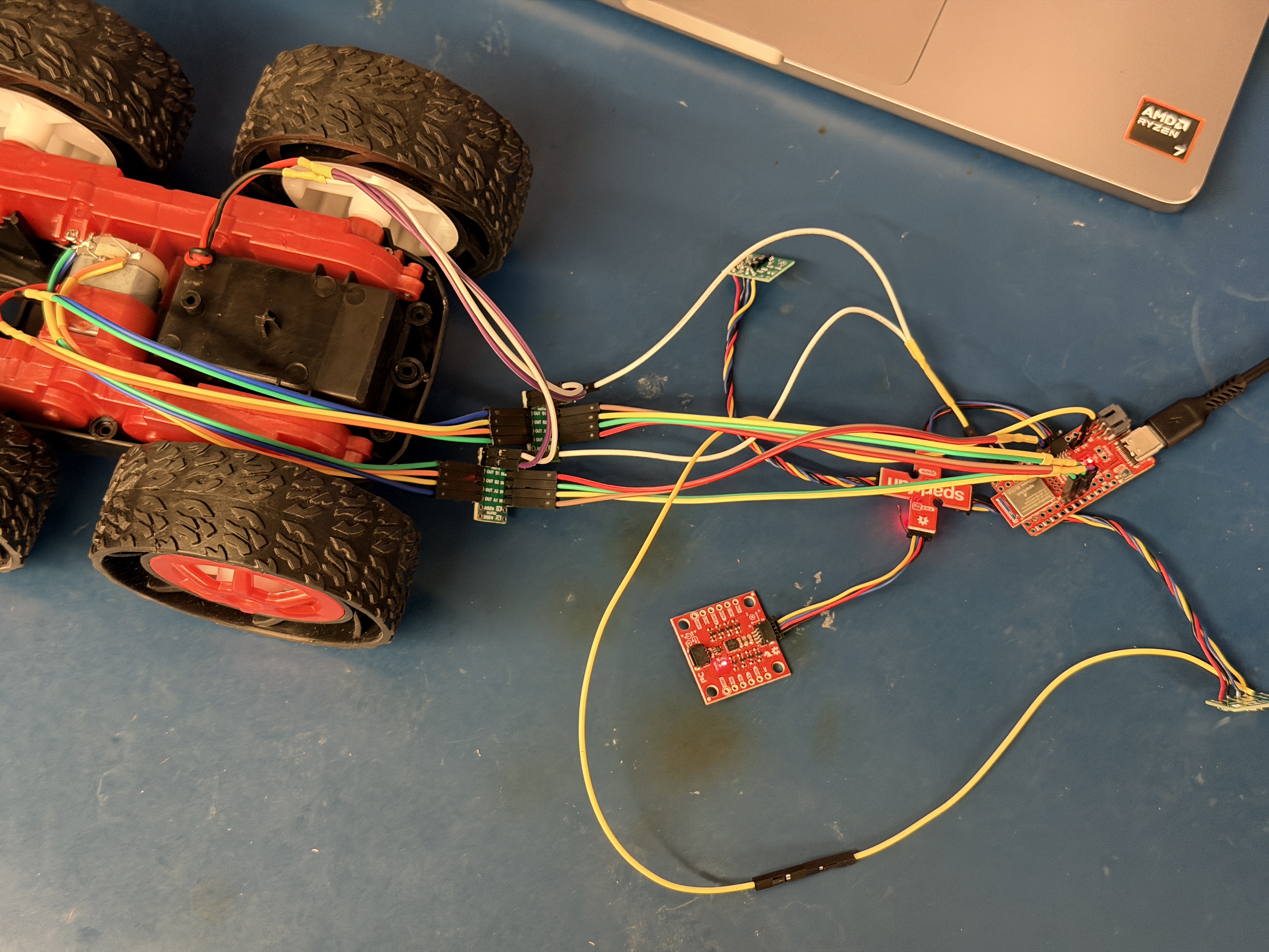
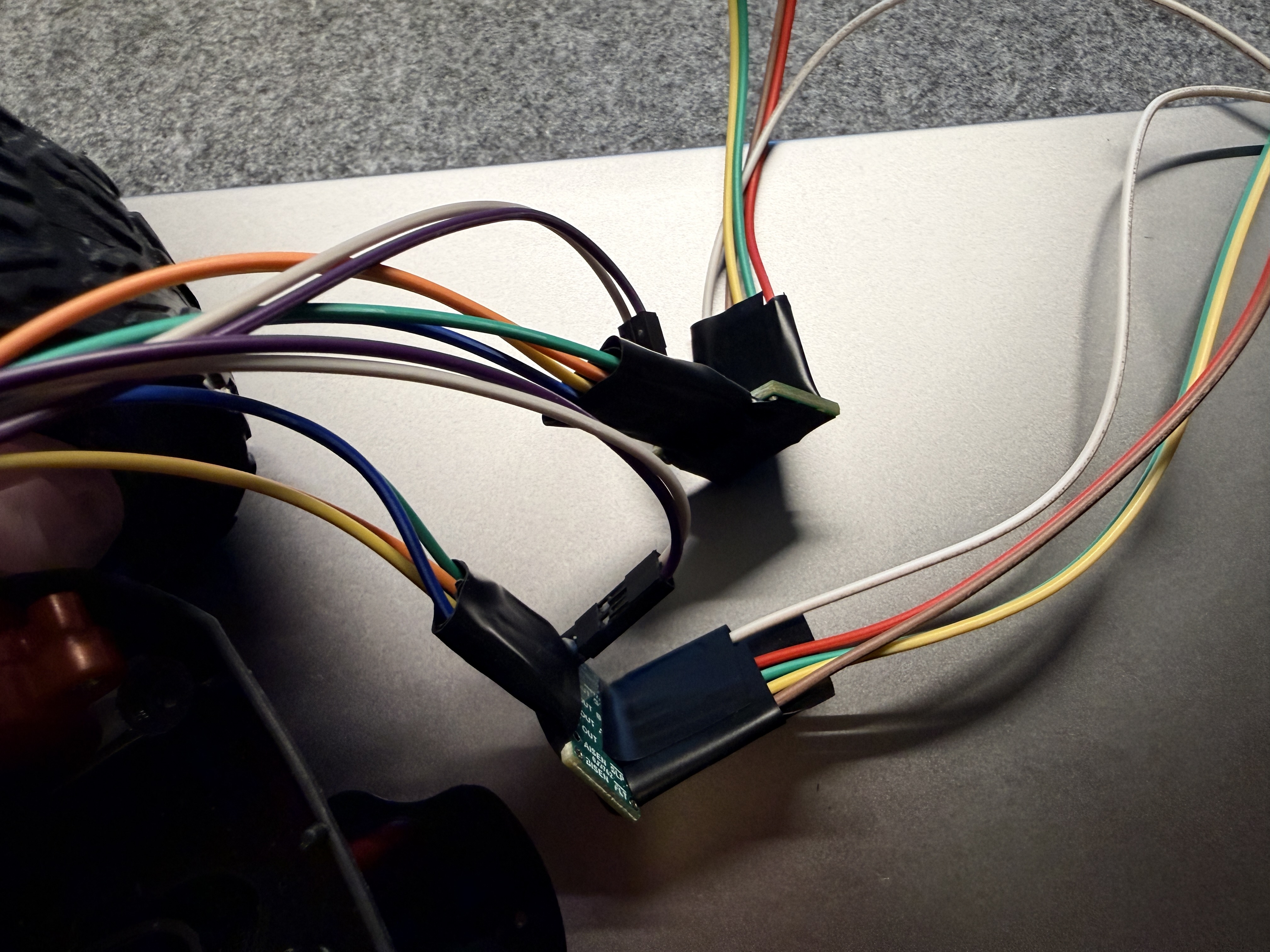
One thing I changed partway through: instead of soldering wires directly to the Artemis pin headers, I switched to pluggable connectors. This made future rewiring much easier and kept the harness clean.
I also 3D-printed crossbeams to mount the circuit boards inside the chassis. The beams hold the boards elevated off the plastic floor and also help resist the chassis from twisting under acceleration. Final cable arrangement before closing everything up:
With the motor driver switched from bench supply to the 850 mAh battery, both wheels spin correctly in both directions:
Lower PWM Limit
To find the minimum PWM values I ran a coarse sweep from PWM 100 down to 15 for forward motion, and from 150 down to 100 for on-axis turns, using IMU data (double-integrated accelerometer for displacement, integrated gyroscope for rotation angle) to objectively detect whether the robot actually moved.
For forward motion, the robot consistently moved at PWM 40, displacing about 2.0 cm in 1 second. Below 40 the displacement stayed under 1.5 cm and wasn’t reliable. The threshold is around 37–40 due to some run-to-run variability from static friction.
For on-axis turns, the robot reliably completed a detectable rotation at PWM 140 (4.6° in 1 second). The 135–139 range was inconsistent, so 140 is the practical minimum.
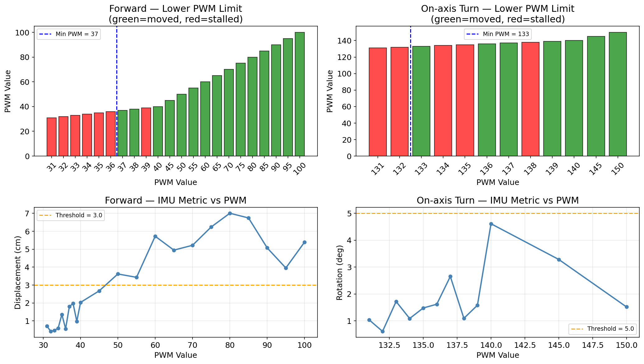
The higher threshold for turns makes sense: in a turn one wheel has to overcome static friction while being driven against the other wheel’s contact patch. That takes more torque than forward motion where both wheels cooperate.
Straight-Line Calibration
Out of the box the car drifted left, which means the right motor is running slightly slower than the left. I added a motorCalFactor that scales the right-motor PWM at every command:
Arduino: calibration factor in motorsForward()
float motorCalFactor = 1.0f;   // set via BLE SET_MOTOR_CAL command

void motorsForward(int speed) {
    int rSpeed = constrain((int)(speed * motorCalFactor), 0, 255);
    analogWrite(L_FWD, speed);  analogWrite(L_BWD, 0);
    analogWrite(R_FWD, rSpeed); analogWrite(R_BWD, 0);
}
I swept through calibration factors over BLE and measured drift direction for each:
| cal_factor | drift |
|---|---|
| 1.00 | left |
| 1.05 | left |
| 1.10 | left |
| 0.95 | none |
A factor of 0.95 slows the right motor by 5%, which compensates for the imbalance. Before calibration:
After setting motorCalFactor = 0.95, the robot tracked straight for over 2 m:
Open Loop Control
The open loop sequence runs entirely on the Artemis after a single BLE trigger. Gyroscope integration handles the 90° turns so they don’t rely on fixed timing.
Arduino: MOTOR_TURN_ANGLE — gyro-controlled turn
case MOTOR_TURN_ANGLE:
{
    int dir, angle;
    if (!robot_cmd.get_next_value(dir)) break;
    if (!robot_cmd.get_next_value(angle)) angle = 90;
    turnTargetDeg    = (float)abs(angle);
    turnAccumDeg     = 0.0f;
    lastTurnGyroTime = millis();
    if (dir == 0) motorsTurnLeft(140);
    else          motorsTurnRight(140);
    motorMode = MOT_TURN_ANGLE;
    break;
}
Python: open loop sequence
MANUAL_PWM = 60
set_motor_cal(0.95)

motor_forward(MANUAL_PWM, 2000)   # forward 2 s
time.sleep(2.5)

motor_turn_angle('right', 90)     # right 90° (gyro-controlled)
time.sleep(0.3)

motor_forward(MANUAL_PWM, 1500)   # forward 1.5 s
time.sleep(2.0)

motor_turn_angle('left', 90)      # left 90° (gyro-controlled)
time.sleep(0.3)

motor_forward(MANUAL_PWM, 2000)   # forward 2 s
time.sleep(2.5)
The right turn landed at −90.5° and the left turn at +90.2°, both very close to target. The car ran the full sequence untethered after the single Python trigger.
Meet my cat Mulberry! 🐱