Lab 5: Linear PID and Linear Interpolation
Goal: drive the robot toward a wall as fast as possible and stop 304 mm away using TOF feedback. I tested P, PD, and PID at three speed levels and added linear extrapolation so the PID loop could run faster than the sensor.
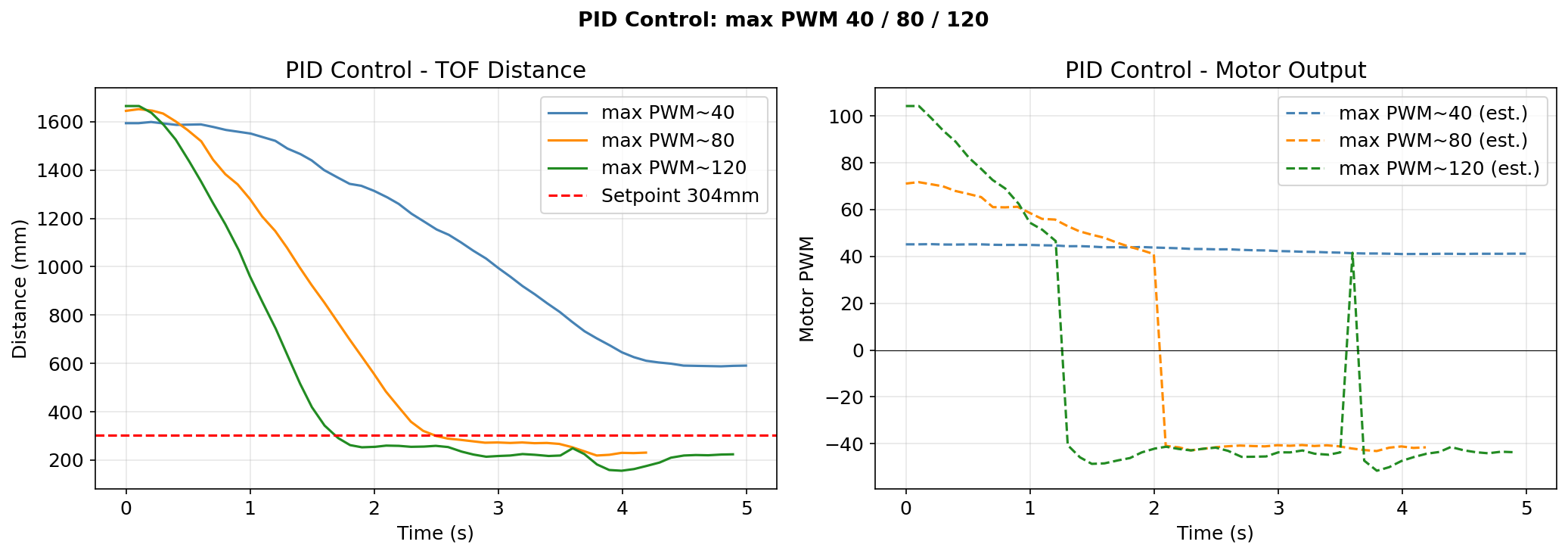
Setup: each run starts 1905 mm from the wall. I put a yoga mat on the wall during high speed tuning. For P, PD, and PID, I tested PWM 40, 80, and 120 with three trials each.
Prelab
Python sends PID_START to reset the controller and start a fixed 10 s run. Artemis logs every TOF sample and PID step into arrays, then GET_PID_DATA streams TOF|dist_mm|extrap_flag|time_ms, PID|error_mm|motor_pwm|time_ms, and PID_END|tof_count|pid_count. Python stores each line and parses the TOF and PID tables after PID_END. I tuned gains over BLE with SET_PID_GAINS, so no reflashing was needed.
Arduino: GET_PID_DATA packet format
case GET_PID_DATA:
{
    for (int i = 0; i < pid_tof_pos; i++) {
        tx_estring_value.clear();
        tx_estring_value.append("TOF|");
        tx_estring_value.append((int)pid_tof_dist[i]);
        tx_estring_value.append("|");
        tx_estring_value.append((int)pid_tof_extrap[i]);
        tx_estring_value.append("|");
        tx_estring_value.append((int)pid_tof_t[i]);
        tx_characteristic_string.writeValue(tx_estring_value.c_str());
        BLE.poll();
    }
    for (int i = 0; i < pid_e_pos; i++) {
        tx_estring_value.clear();
        tx_estring_value.append("PID|");
        tx_estring_value.append((int)pid_e_hist[i]);
        tx_estring_value.append("|");
        tx_estring_value.append((int)pid_motor_hist[i]);
        tx_estring_value.append("|");
        tx_estring_value.append((int)pid_t_hist[i]);
        tx_characteristic_string.writeValue(tx_estring_value.c_str());
        BLE.poll();
    }
    tx_estring_value.clear();
    tx_estring_value.append("PID_END|");
    tx_estring_value.append(pid_tof_pos);
    tx_estring_value.append("|");
    tx_estring_value.append(pid_e_pos);
    tx_characteristic_string.writeValue(tx_estring_value.c_str());
    break;
}
Python: notification handler and parser
_pid_buf, _pid_done = [], False

def _pid_notify_handler(uuid, bytearray_data):
    global _pid_buf, _pid_done
    line = ble.bytearray_to_string(bytearray_data).strip()
    _pid_buf.append(line)
    if line.startswith("PID_END"):
        _pid_done = True

def parse_pid_data(buf):
    tof_rows, pid_rows = [], []
    for line in buf:
        if line.startswith("TOF|"):
            _, dist, extrap, t = line.split("|")
            tof_rows.append((int(dist), bool(int(extrap)), int(t)))
        elif line.startswith("PID|"):
            _, err, pwm, t = line.split("|")
            pid_rows.append((int(err), int(pwm), int(t)))
    return tof_rows, pid_rows
TOF Sensor Configuration
I kept the default TOF integration time. Real readings arrived at about 10 Hz. The PID loop ran at about 112 Hz because it never blocked on sensor readiness, so extrapolation filled the gaps. setProxIntegrationTime could raise the sensor rate, but 10 Hz was enough for a 1905 mm approach.
Controller Choice
I expected PD to do most of the work. P drives the robot toward the wall, and D should brake earlier at high speed and reduce overshoot. I left I for last because it is the easiest term to over-tune with wind-up. So I tuned P first, added D to stop the crashes, then added a small I term to remove the last bias.
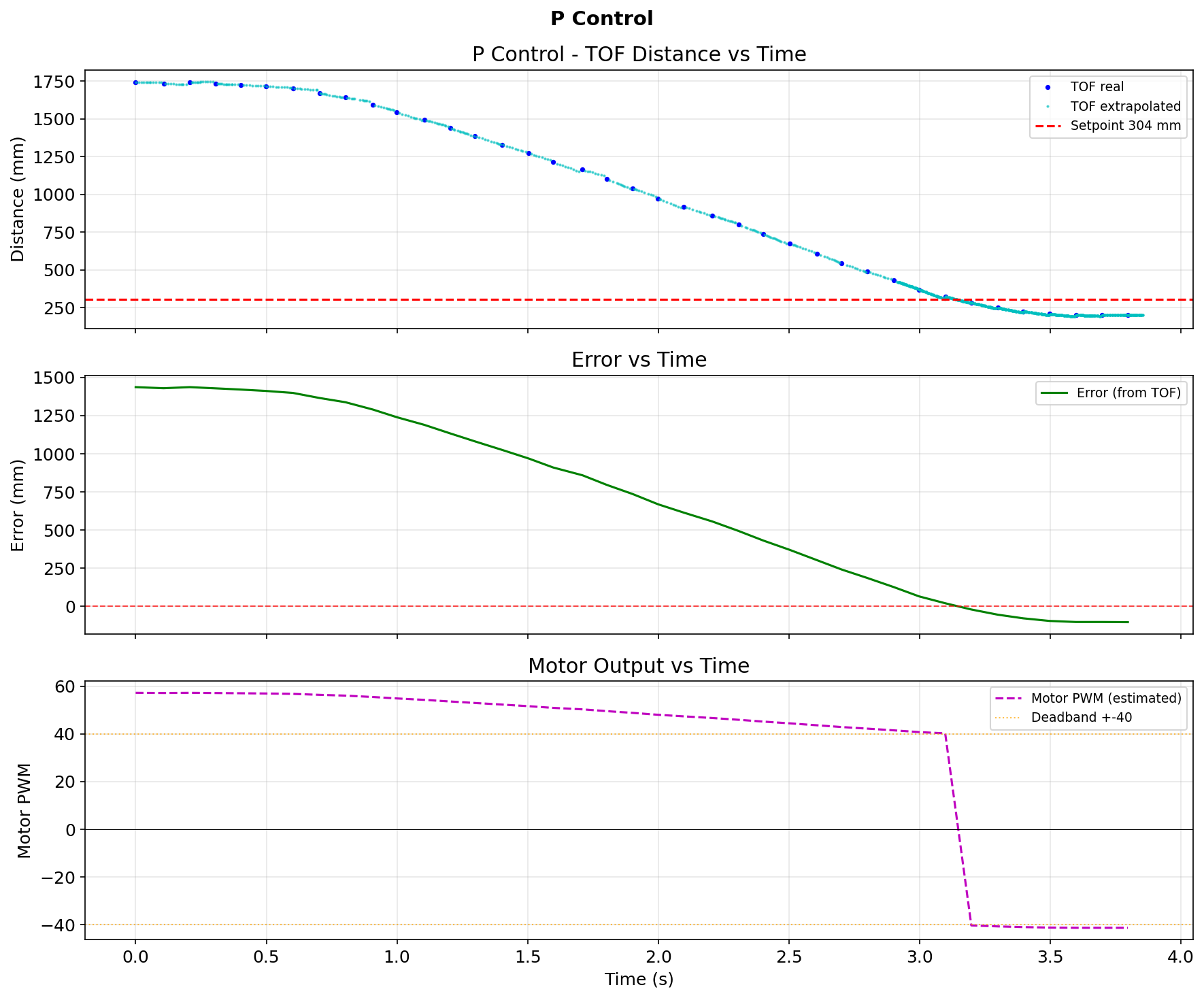
P Control
The firmware maps PID output to PWM with PWM = 40 + (|output| / 200) * 160. To cap early tuning near 60 PWM, I wanted a max output near 25, so KP = 25 / 1700 ≈ 0.015 using a typical starting error of 1700 mm.
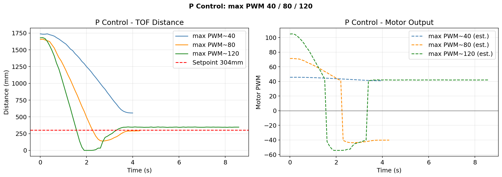
At 40 PWM the robot coasted and usually stopped 50 to 100 mm past the target. At 80 PWM it needed reverse braking and usually stopped cleanly. At 120 PWM, P alone could not brake fast enough and hit the wall every run. The logged P run ended at -104 mm error.
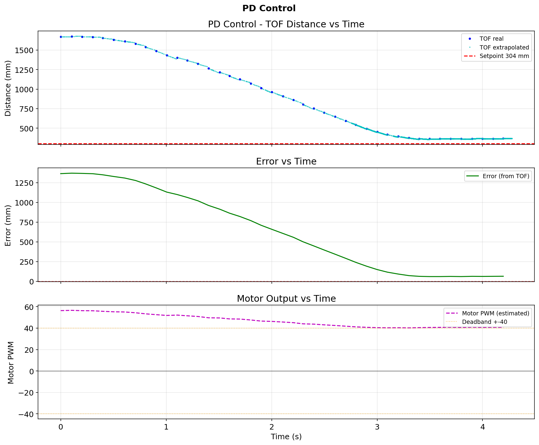
PD Control
Adding KD = 0.004 fixed the high speed crashes. The derivative term sees the fast negative distance change and commands braking proportional to approach speed. I filtered it with pid_dF = 0.9 * pid_dF + 0.1 * d_raw to suppress noise.
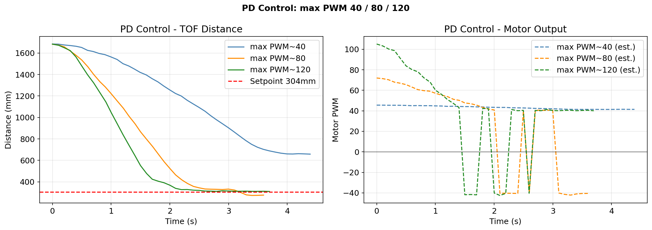
At 120 PWM, PD braked smoothly and stopped within 21 mm of the setpoint. The motor plot shows active reverse braking that P could not produce. PD was already close to PID at all three speeds, so D did most of the useful extra work.
PID Control
I added PID to test whether a small integrator could remove the last steady state error without hurting the transient. KI = 0.001 was enough, and the clamp at ±1000 mm·s prevented wind-up. The logged PID run ended at -18 mm, compared with -104 mm for P and +21 mm for PD. PD gave most of the improvement, while PID only cleaned up the last small offset.
Arduino: full PID computation in handle_pid()
float e = tof_current - (float)pid_setpoint;

// Integral with wind-up clamp
pid_I += e * (float)dt / 1000.0f;
if (pid_I >  1000.0f) pid_I =  1000.0f;
if (pid_I < -1000.0f) pid_I = -1000.0f;

// Derivative with LPF (alpha = 0.9)
float d_raw = (e - pid_last_e) / ((float)dt / 1000.0f);
pid_dF = 0.9f * pid_dF + 0.1f * d_raw;
pid_last_e = e;

float output = pid_kp * e + pid_ki * pid_I + pid_kd * pid_dF;
output = constrain(output, -200.0f, 200.0f);

// Deadband mapping: skip the dead zone [0, 40 PWM]
if (fabsf(output) > 2.0f) {
    float mapped = 40.0f + (fabsf(output) / 200.0f) * 160.0f;
    pwm = (int)constrain(mapped, 40.0f, 200.0f);
    if (output > 0) motorsForward(pwm);
    else { motorsBackward(pwm); pwm = -pwm; }
} else {
    motorsStop();
}
For robustness, I pushed the robot away from the wall mid-run. PID corrected and returned to 304 mm.
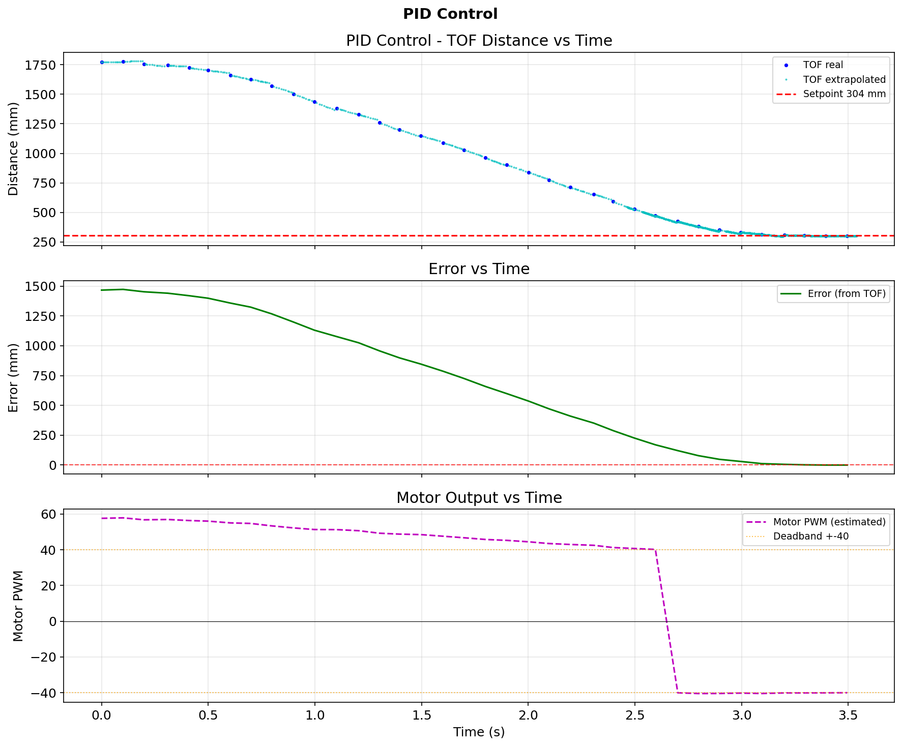
| Controller | KP | KI | KD | Final error |
|---|---|---|---|---|
| P | 0.015 | 0 | 0 | -104 mm |
| PD | 0.015 | 0 | 0.004 | +21 mm |
| PID | 0.015 | 0.001 | 0.004 | -18 mm |
Linear Extrapolation
The TOF sensor gives real data at 10 Hz, but the PID loop runs at 112 Hz. Without extrapolation, the derivative sees stale error for about 90% of the loop. I fixed that by estimating the current distance from the last two real TOF readings.
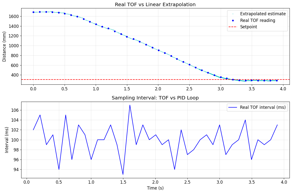
Each new TOF sample updates the slope in mm/ms. Between samples, Artemis projects forward with tof_current = tof_last_val + tof_slope * dt_since. I also logged an extrap flag so the plots can separate real and estimated points. This gives an effective 11.2x loop speed-up, so the derivative gets a fresh estimate every iteration instead of waiting for the next sensor sample.
With an 80 mm wheel diameter, the circumference is about 251.3 mm. In the fastest successful run, the robot traveled about 1601 mm from 1905 mm to 304 mm in 3.97 s, so the average speed was about 403.6 mm/s, or 0.404 m/s and 1.32 ft/s. That is about 1.61 wheel rev/s, or 96.4 rpm. If speed scales roughly with cruise PWM in this region, the same estimate gives about 0.269 m/s at 80 PWM and 0.135 m/s at 40 PWM.
Arduino: TOF extrapolation in handle_pid()
if (tofSensor1.checkForDataReady()) {
    float new_dist = (float)tofSensor1.getDistance();
    tofSensor1.clearInterrupt();
    unsigned long t_new = millis();
    if (tof_extrap_valid) {
        float dt_tof = (float)(t_new - tof_last_t_ms);
        if (dt_tof > 0.5f)
            tof_slope = (new_dist - tof_last_val) / dt_tof;
    }
    tof_last_val = new_dist;
    tof_last_t_ms = t_new;
    tof_extrap_valid = true;
    tof_current = new_dist;
} else if (tof_extrap_valid) {
    float dt_since = (float)(millis() - tof_last_t_ms);
    tof_current = tof_last_val + tof_slope * dt_since;
}
Meet with my cat Mulberry! 🐱