Lab 6: Orientation Control
Goal: control robot yaw in place using gyroscope feedback and PID. I tested P, PD, and PID, handled derivative kick with a low-pass filter, and changed the setpoint live over BLE.
Prelab
The BLE flow mirrors Lab 5. Python sends ORIENT_START to reset yaw and start the PID loop, which stops on timeout. Artemis buffers each PID sample into arrays. After ORIENT_STOP and GET_ORIENT_DATA, it streams tagged strings. Gains and setpoint can be updated mid-run with SET_ORIENT_GAINS and SET_ORIENT_TARGET, so no reflashing is needed.
Data format:
OPID|{yaw_tenths}|{error_tenths}|{motor_pwm}|{time_ms}
OPID_END|{count}
Yaw and error are sent in tenths of a degree, so 905 means 90.5°. Signed motor PWM gives right turn for positive and left turn for negative.
Arduino: GET_ORIENT_DATA packet format
case GET_ORIENT_DATA:
{
    for (int i = 0; i < orient_pos; i++) {
        tx_estring_value.clear();
        tx_estring_value.append("OPID|");
        tx_estring_value.append((int)(orient_yaw_hist[i] * 10));
        tx_estring_value.append("|");
        tx_estring_value.append((int)(orient_err_hist[i] * 10));
        tx_estring_value.append("|");
        tx_estring_value.append((int)orient_motor_hist[i]);
        tx_estring_value.append("|");
        tx_estring_value.append((int)orient_t_hist[i]);
        tx_characteristic_string.writeValue(tx_estring_value.c_str());
        BLE.poll();
    }
    tx_estring_value.clear();
    tx_estring_value.append("OPID_END|");
    tx_estring_value.append(orient_pos);
    tx_characteristic_string.writeValue(tx_estring_value.c_str());
    break;
}
Python: notification handler and parser
_orient_buf  = []
_orient_done = False

def _orient_notify_handler(uuid, bytearray_data):
    global _orient_buf, _orient_done
    line = ble.bytearray_to_string(bytearray_data).strip()
    _orient_buf.append(line)
    if line.startswith('OPID_END'):
        _orient_done = True

def parse_orient_data(buf):
    rows = []
    for line in buf:
        if line.startswith('OPID|'):
            parts = line.split('|')
            if len(parts) == 5:
                rows.append({
                    'yaw_deg':   int(parts[1]) / 10.0,
                    'error_deg': int(parts[2]) / 10.0,
                    'motor_pwm': int(parts[3]),
                    'time_ms':   int(parts[4]),
                })
    df = pd.DataFrame(rows)
    if len(df) > 0:
        df['time_s'] = (df['time_ms'] - df['time_ms'].min()) / 1000.0
    return df
run_orient_experiment() sends ORIENT_START, can send SET_ORIENT_TARGET mid-run, then calls ORIENT_STOP, GET_ORIENT_DATA, and waits for OPID_END. BLE stays responsive because Artemis only logs during the run.
Gyro Integration and Sensor Considerations
I used the onboard DMP to get yaw directly, which avoids drift from raw gyro integration. The ICM-20948 default gyro range is ±250 °/s, which is enough for my turns. The DMP quaternion is converted to startup-relative yaw.
If yaw is computed by integrating raw gyro rate, even a small constant bias produces an angle error that grows roughly linearly with time, so long runs drift noticeably. The ICM-20948 gyro range is configurable up to ±2000 °/s in software, and that maximum is still far above the turn rate of this robot.
The PID loop averaged 4.5 ms, or about 220 Hz, above the DMP output rate of about 100 Hz.
I clamp error to [-180°, 180°] so the robot always takes the shortest turn. Otherwise, 181° and -179° would command opposite directions for nearly the same orientation. The DMP also reduces tilt sensitivity and repeated-run yaw drift.
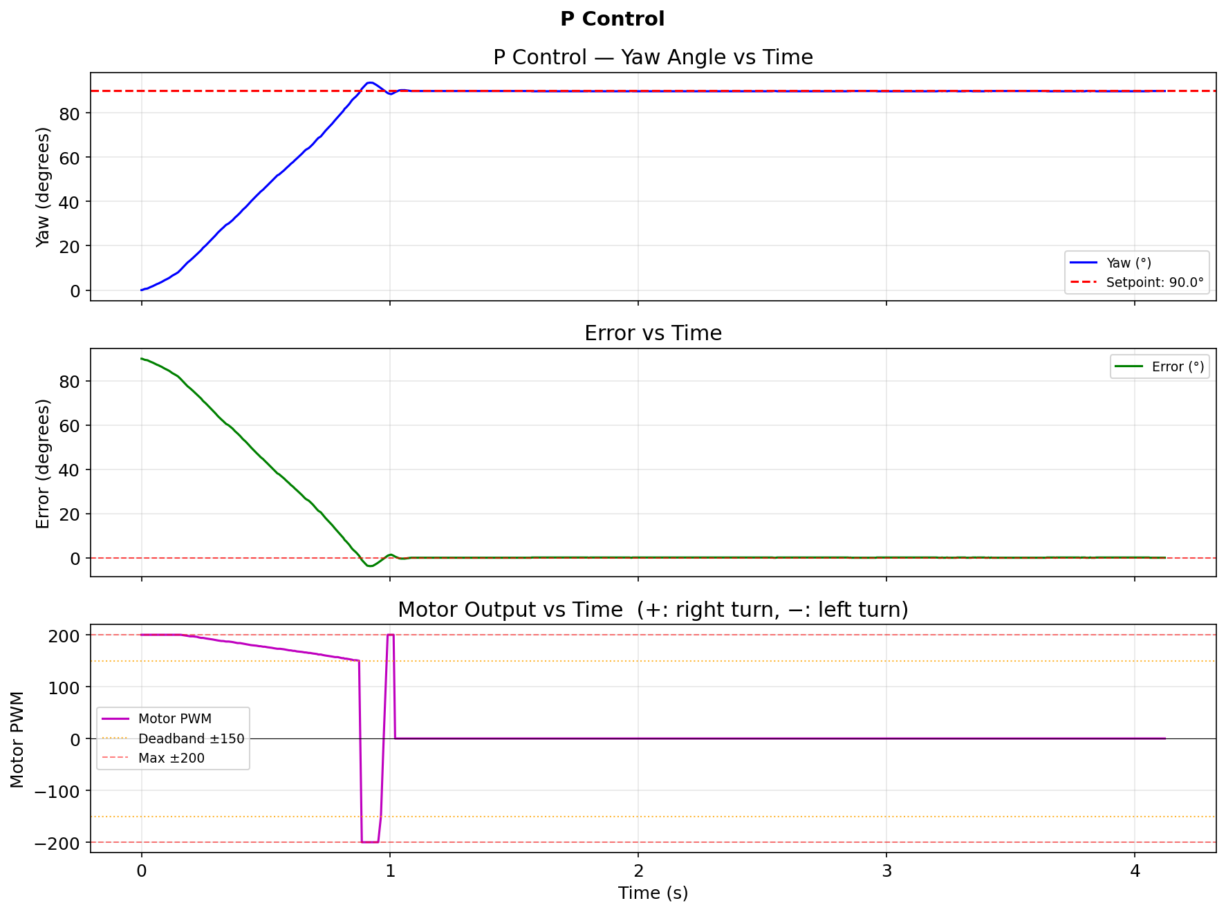
P Control
At 180° error I wanted near maximum turn speed. Motor PWM is mapped into [110, 166] after the deadband, so KP = 166 / 180 ≈ 0.92 was the rough starting point. I tuned empirically and settled on KP = 2.5.
With KP = 2.5 and a 90° target, the robot reached 90° in about 1.0 s and settled to +0.1° error after overshooting to about 93.7°. The run logged 966 samples over 4.1 s, so the average loop interval was 4.3 ms, or 234 Hz.
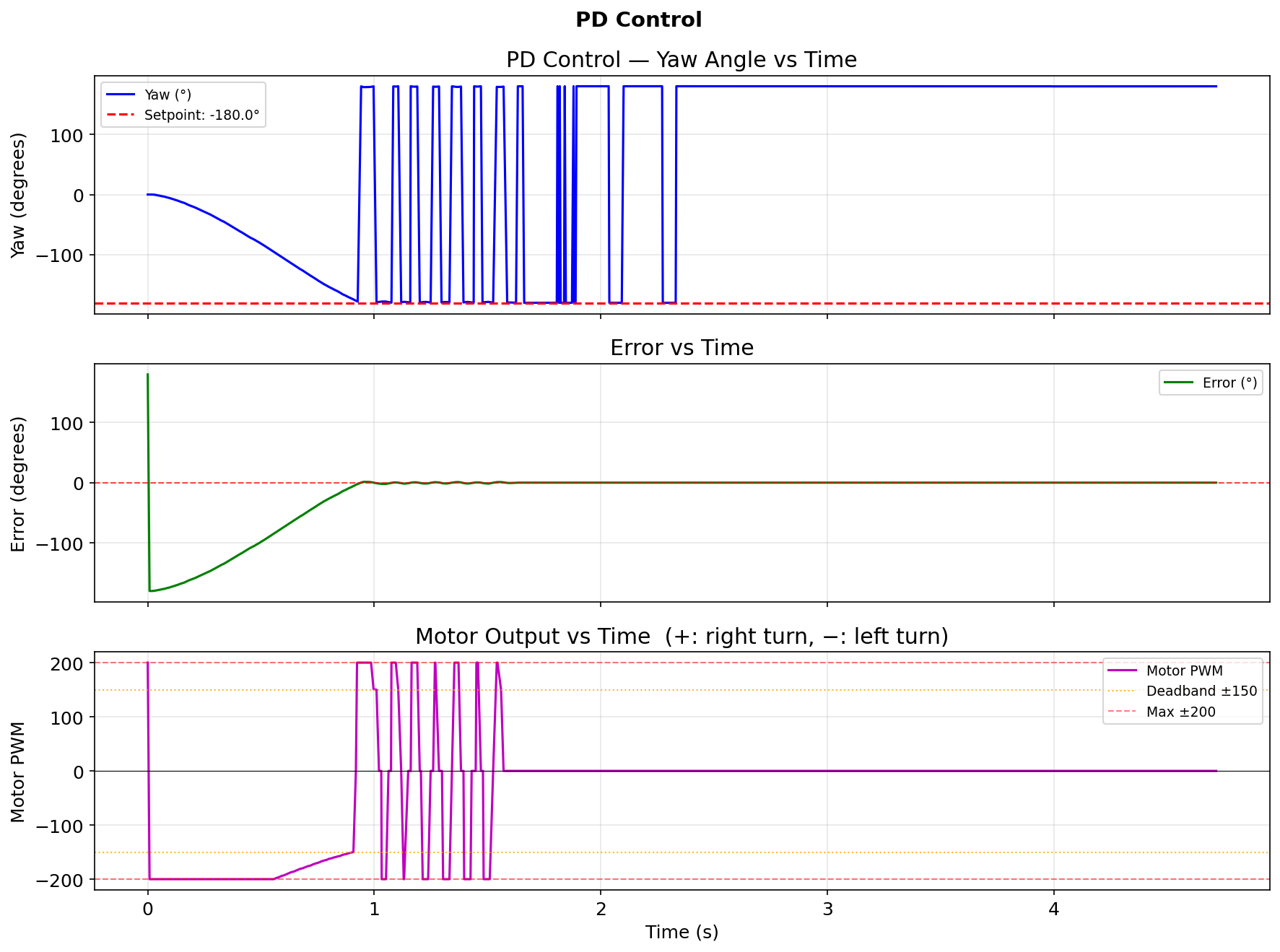
PD Control
The derivative term damps fast rotation and reduces overshoot. Since yaw is the integral of angular velocity, the derivative of yaw error is signed angular velocity.
I set KD = 0.05. My first try used KD = 0.4, but at 300 °/s the D term alone added 120 PWM, overpowered P below 48° error, and caused oscillation. Dropping to 0.05 gave clean settling.
I tested target = -180° to check wrap-around. The robot chose the left turn, crossed -180° and +180° cleanly, and stopped at 179.9° with +0.1° final error. The 982-sample run averaged 4.8 ms, or 208 Hz.
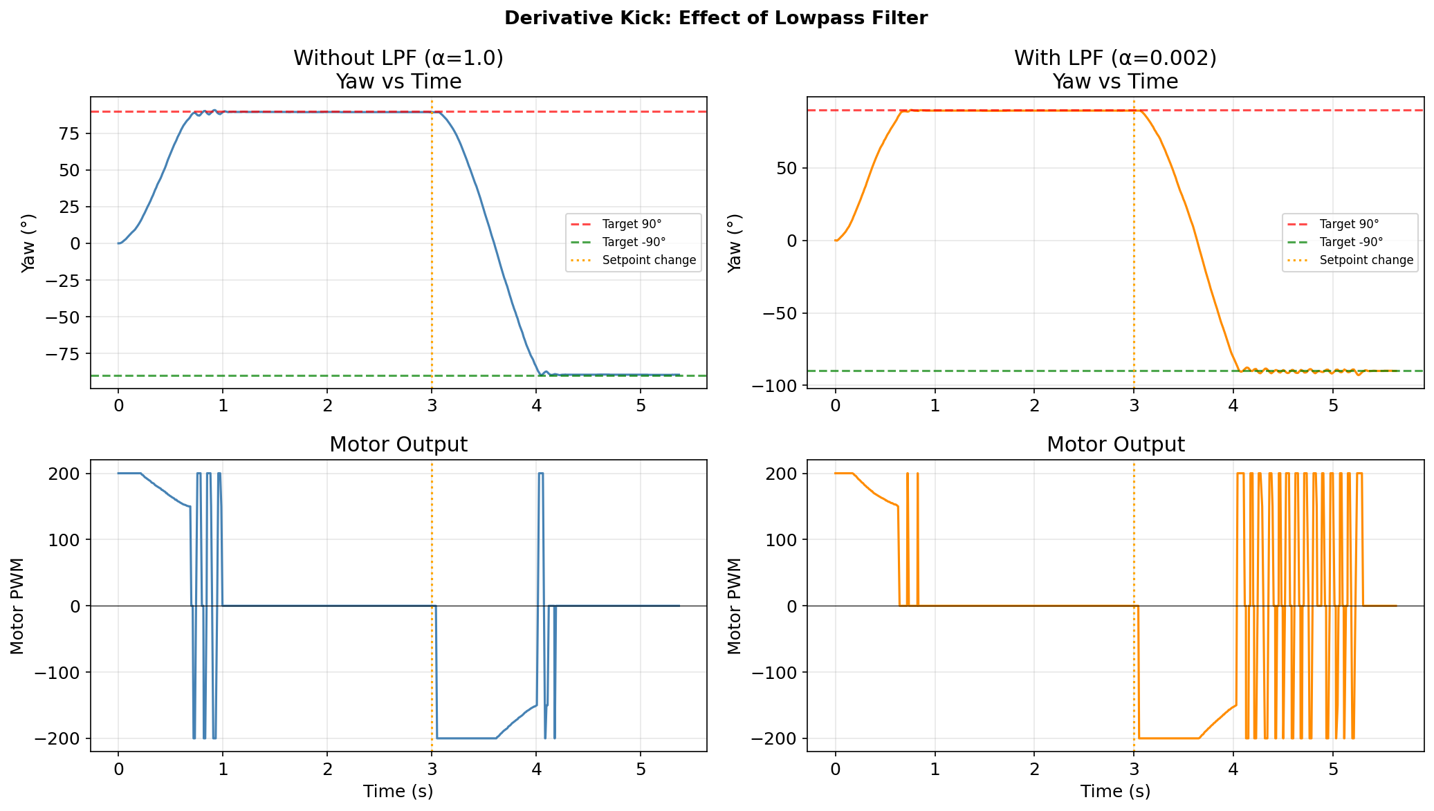
Derivative Kick and Lowpass Filter
Derivative kick appears when the setpoint changes instantly mid-run. The error jumps in one PID step, so the derivative spikes and can drive the motor to maximum for one sample. I fixed this with a low-pass filter:
orient_dF = alpha * d_raw + (1.0f - alpha) * orient_dF;
With alpha = 1.0, the spike passes through. With alpha = 0.002, the derivative moves by only 0.2% of the raw value per step, so the kick is almost gone.
I ran the same sequence twice: hold 90° for 3 s, then switch to -90°. Without the filter, motor PWM spiked to ±200 at the switch. With alpha = 0.002, the transition stayed smooth.
Arduino: derivative LPF in orientation PID
float d_raw = (orient_error - orient_last_e) / ((float)dt / 1000.0f);
orient_dF = ORIENT_ALPHA * d_raw + (1.0f - ORIENT_ALPHA) * orient_dF;
orient_last_e = orient_error;

float output = orient_kp * orient_error
             + orient_ki * orient_I
             + orient_kd * orient_dF;
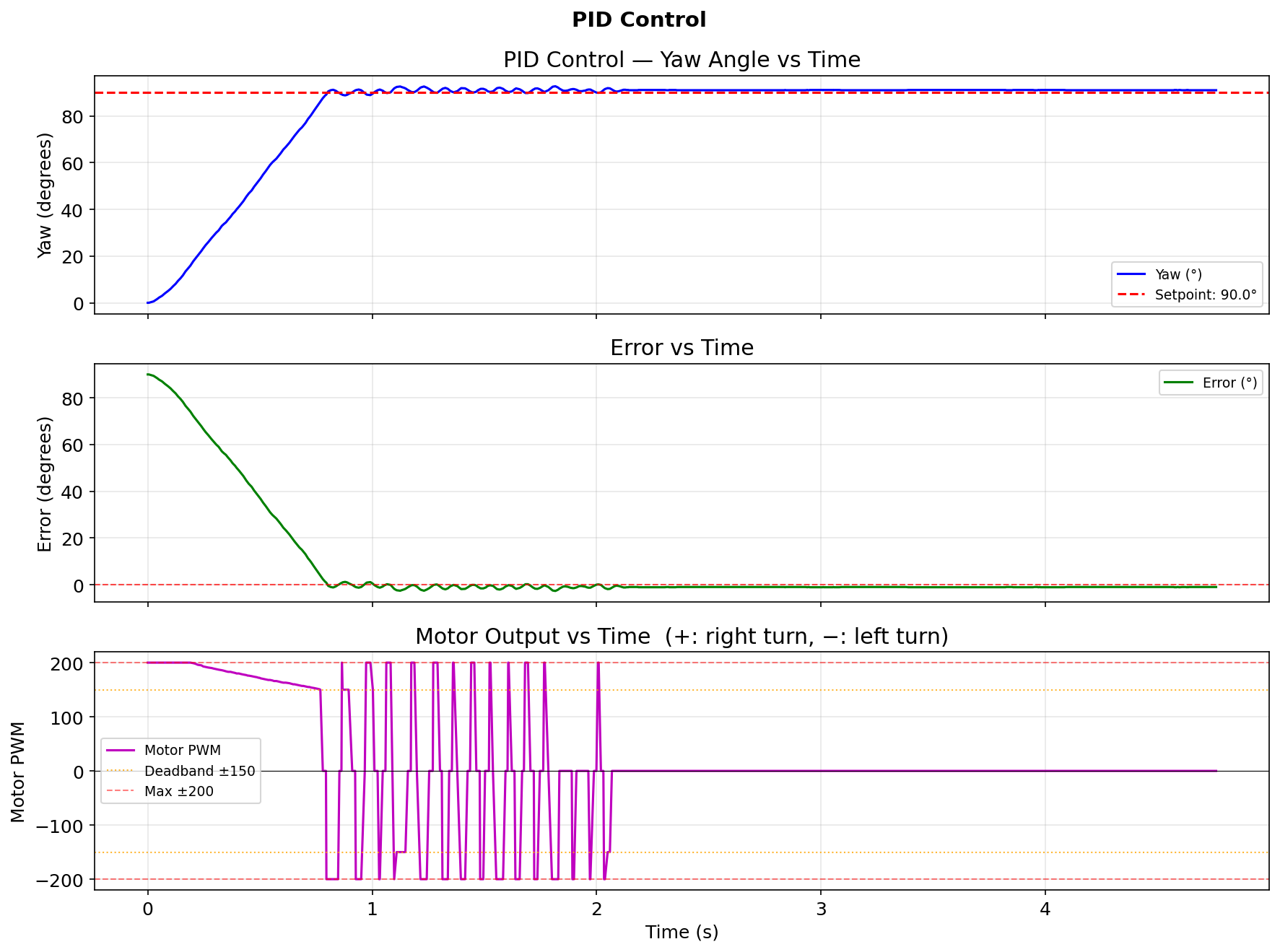
PID Control
The integral term removes steady state error from friction. If the robot stops slightly off target and P plus D are too small to move it, I builds command until it clears the deadband. I used KI = 0.05.
The 90° PID run ended at -1.0° error, compared with +0.1° for P only. The extra 1° overshoot means the integrator was still accumulating when the robot stopped, so a tighter wind-up clamp would help. The run averaged 4.7 ms, or 213 Hz, over 1015 samples.
Arduino: full orientation PID computation
// Clamp error to [-180, 180] for shortest-path rotation
float orient_error = orient_target - orient_yaw;
while (orient_error >  180.0f) orient_error -= 360.0f;
while (orient_error < -180.0f) orient_error += 360.0f;

// Integral with wind-up clamp
orient_I += orient_error * ((float)dt / 1000.0f);
if (orient_I >  ORIENT_IMAX) orient_I =  ORIENT_IMAX;
if (orient_I < -ORIENT_IMAX) orient_I = -ORIENT_IMAX;

// Derivative with LPF
float d_raw = (orient_error - orient_last_e) / ((float)dt / 1000.0f);
orient_dF = ORIENT_ALPHA * d_raw + (1.0f - ORIENT_ALPHA) * orient_dF;
orient_last_e = orient_error;

float output = orient_kp * orient_error
             + orient_ki * orient_I
             + orient_kd * orient_dF;
output = constrain(output, -200.0f, 200.0f);

// Deadband mapping into [TURN_MIN=110, TURN_MAX=166]
if (fabsf(output) > 2.0f) {
    float mapped = 110.0f + (fabsf(output) / 200.0f) * 56.0f;
    int pwm = (int)constrain(mapped, 110.0f, 166.0f);
    if (output > 0) motorsTurnRight(pwm);
    else            motorsTurnLeft(pwm);
} else {
    motorsStop();
}
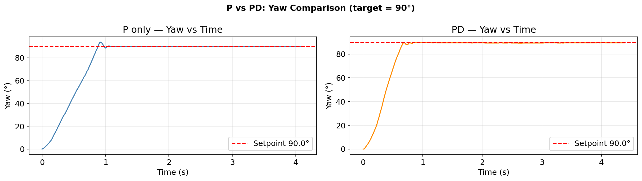
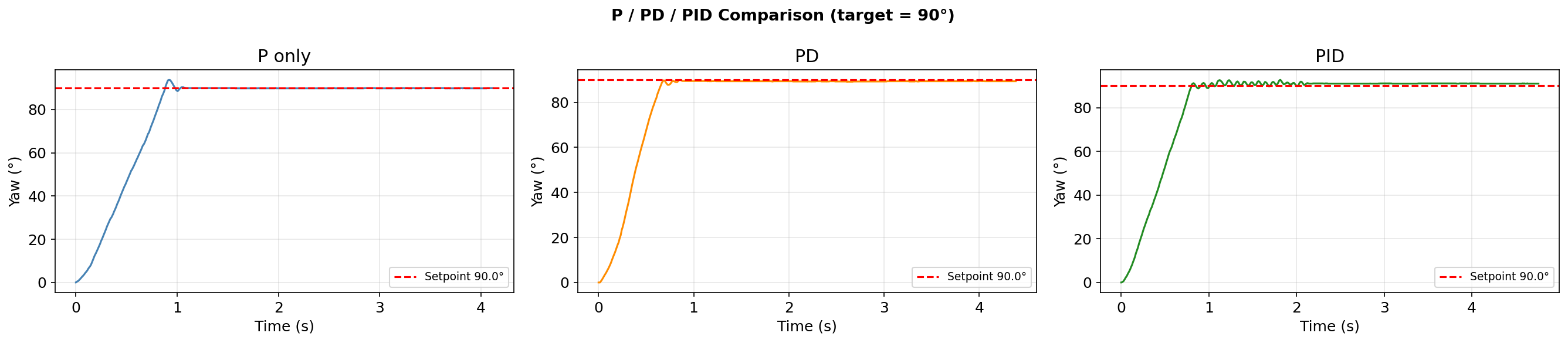
The three-way comparison shows P and PD settle similarly fast, while PID removes the residual offset from surface friction.
| Controller | KP | KI | KD | Final error | Avg loop |
|---|---|---|---|---|---|
| P | 2.5 | 0 | 0 | +0.1° | 4.3 ms |
| PD | 2.5 | 0 | 0.05 | +0.6° | 4.4 ms |
| PID | 2.5 | 0.05 | 0.05 | -1.0° | 4.7 ms |
P control was already enough for this task and even beat PD and PID in final error. I think that happened because turning in place on flat ground is simpler than high speed wall approach, so extra I and D added little here. On rough ground or in faster motion, PID would matter more.
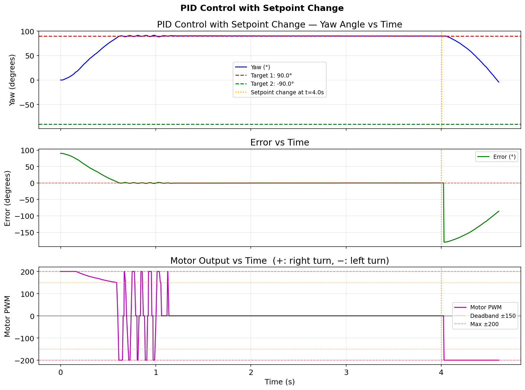
Setpoint Change Mid-Run
To verify live setpoint updates, I started at 90°, let the robot settle, then sent SET_ORIENT_TARGET -90 over BLE at t = 4 s while the PID loop was still running. The robot reached 89.9° first, then turned toward -90°.
The same structure extends to driving by adding the orientation PID output as a signed steering correction on top of a forward or backward base motor command.
Arduino: SET_ORIENT_TARGET command handler
case SET_ORIENT_TARGET:
{
    float new_target;
    success = robot_cmd.get_next_value(new_target);
    if (success) {
        orient_target = new_target;
        tx_estring_value.clear();
        tx_estring_value.append("ORIENT_TARGET|");
        tx_estring_value.append(orient_target);
        tx_characteristic_string.writeValue(tx_estring_value.c_str());
    }
    break;
}
The setpoint is global, so a BLE write takes effect on the next cycle. No synchronization is needed because Artemis is single-threaded.
Meet with my cat Mulberry! 🐱