Lab 9: Mapping
Goal
The goal of this lab was to build a static room map from several marked robot positions, transform every ToF reading into the room frame, and convert the point cloud into a line based map for later localization and planning. I used orientation control. The robot turned in small angular steps, stopped, measured distance, and then turned to the next heading.
I scanned the four required points (5, -3), (-3, -2), (0, 3), and (5, 3). I also added (0, 0) to improve the merged map.
Sensing And Control
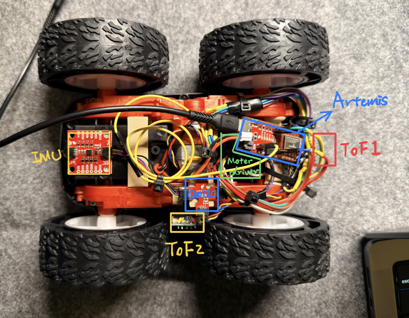
I chose the right ToF sensor instead of the front sensor because it is closer to the robot center. That reduces the position error caused by any small off axis rotation. It also makes the measured angle more faithful during a turn. The sensor placement is shown below.
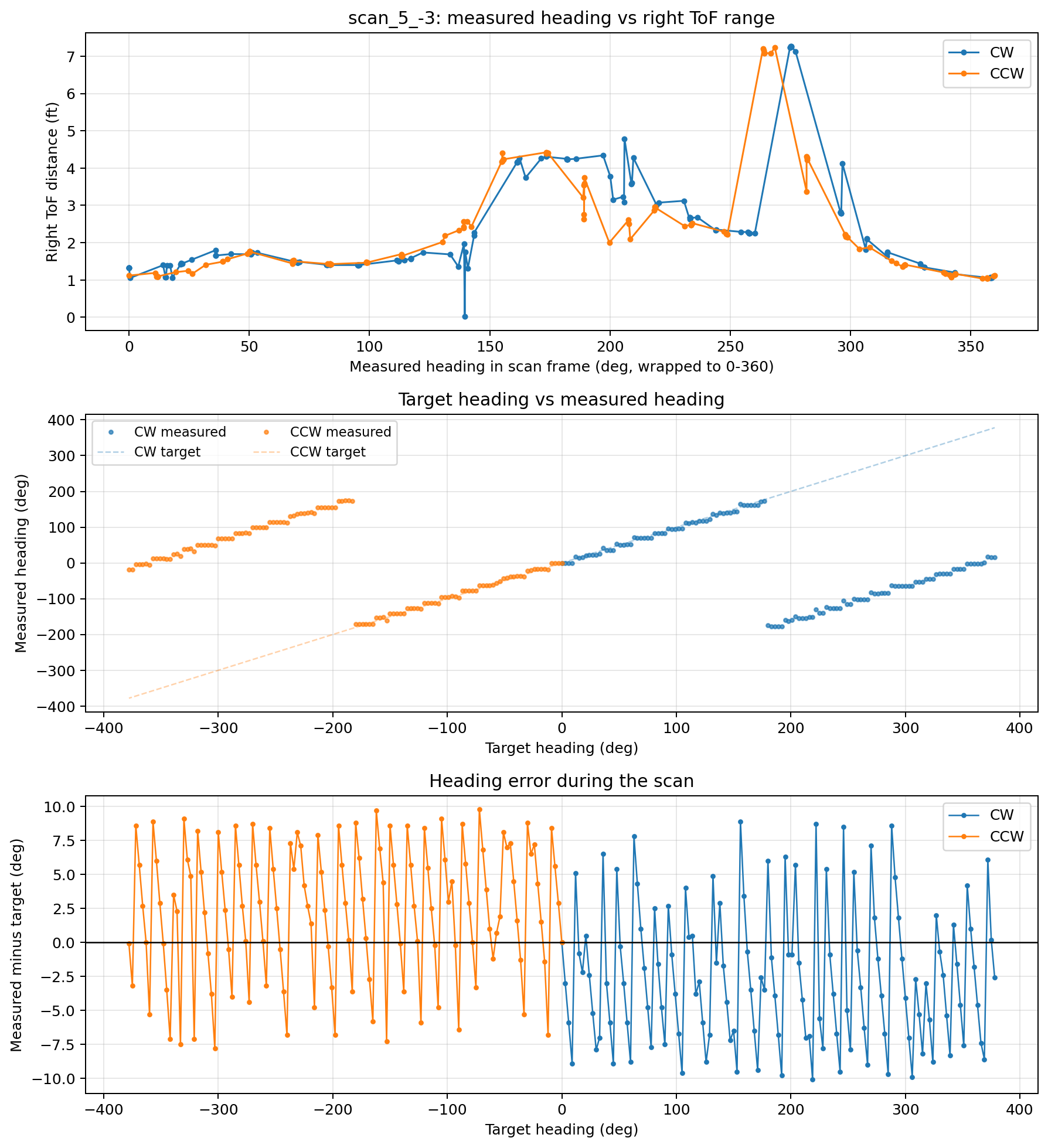
For control, I used PID orientation control with a 3 degree target spacing and a 380 degree sweep. I overswept by 20 degrees because static friction sometimes caused the last part of a 360 degree turn to come up short. Each pass therefore targeted 127 headings. I started every scan from the same room reference direction, then applied only rigid per scan heading corrections during post processing. I ran both clockwise and counterclockwise passes at each location to check repeatability. Across the final 10 passes, the robot collected 1270 right sensor samples and all 1270 were valid. The mean absolute heading error averaged 4.51 degrees, and the worst case heading error was 10.2 degrees.
The lab also asked for an estimate of map error from orientation control. In the middle of a 4 x 4 m empty room, the wall would be about 2 m away. Using the measured heading error only, the average lateral error would be about 0.157 m, and the worst case lateral error would be about 0.354 m. That rough upper bound matches the final map.
One thing I had to correct during post processing was the room frame start heading for each scan. I first assumed every scan started with the same room heading, but the actual robot placement differed by 90 degrees at several locations. I fixed that with rigid per scan theta corrections in the notebook. I did not scale any scan.
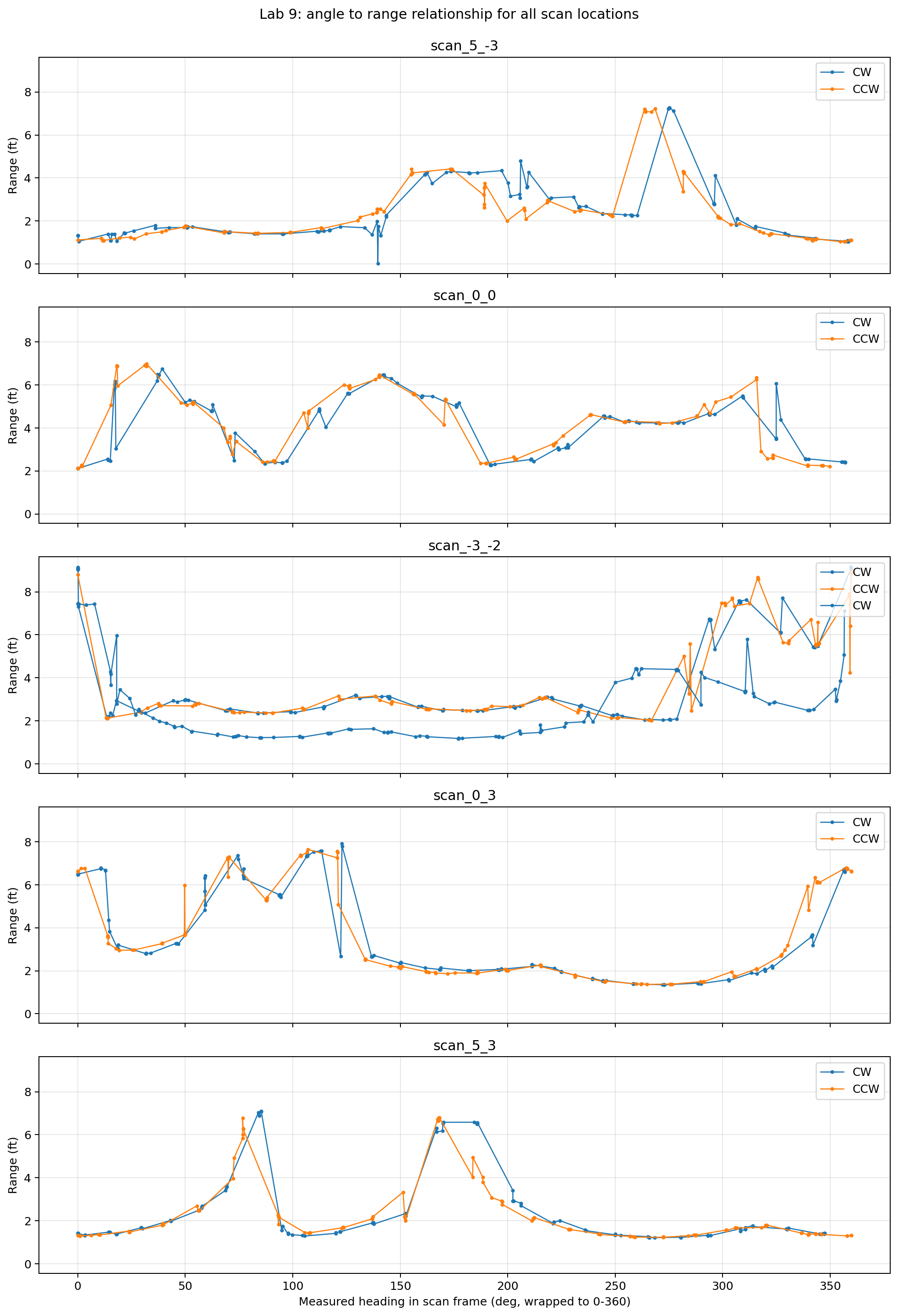
The figure below shows the direct relationship between angle and measured distance for all five locations. Each subplot overlays the clockwise and counterclockwise passes. The measured heading stayed close to the commanded heading, so I trusted logged IMU heading instead of assuming perfectly uniform angular spacing. The map used only fresh right ToF readings while the robot was stopped. I did not use Kalman extrapolation.
Code
Arduino: step and stop mapping with right ToF only
bool read_map_tof_sample(int &front_mm, int &right_mm, unsigned long &ts_ms) {
    float right_dist = 0.0f;
    if (!read_right_tof_sample(right_dist, ts_ms)) return false;

    front_mm = -1;
    right_mm = (int)right_dist;
    return true;
}

void handle_map() {
    if (runMode != RUN_MAP) return;

    unsigned long now = millis();
    if (now - map_start_ms >= map_timeout_ms) {
        motorsStop();
        runMode = RUN_IDLE;
        tx_characteristic_string.writeValue("MAP_TIMEOUT");
        return;
    }

    float heading_deg = 0.0f;
    float gyro_dps = imu_last_gyr_z;
    unsigned long heading_ts = now;
    if (!update_drift_heading_state(heading_deg, gyro_dps, heading_ts)) return;

    if (map_phase == 0) {
        float e = 0.0f;
        int pwm = 0;
        if (!step_orient_pid_with_heading(heading_deg, e, pwm, heading_ts, false)) return;

        bool settled = fabsf(e) <= MAP_DONE_BAND_DEG && fabsf(gyro_dps) <= MAP_DONE_GYRO_DPS;
        map_done_count = settled ? (map_done_count + 1) : 0;

        if (map_done_count >= MAP_DONE_COUNT) {
            motorsStop();
            map_sample_wait_start_ms = heading_ts;
            map_phase = 1;
        }
        return;
    }

    if (map_phase == 1) {
        int front_mm = -1;
        int right_mm = -1;
        unsigned long tof_ts = heading_ts;
        if (read_map_tof_sample(front_mm, right_mm, tof_ts)) {
            finish_map_sample(heading_deg, front_mm, right_mm, tof_ts);
            return;
        }
    }
}
Python: BLE callback, parsing, and map collection
_map_buf = []
_map_done = False

def map_notify_handler(uuid, bytearray_data):
    global _map_buf, _map_done
    msg = ble.bytearray_to_string(bytearray_data).strip()
    _map_buf.append(msg)
    if msg.startswith('MAP_END|'):
        _map_done = True

def parse_map_messages(messages, scan_name='scan', turn_dir=TURN_DIR_CW, pass_name='pass'):
    rows = []
    for msg in messages:
        if msg.startswith('MAP|'):
            parts = msg.split('|')
            rows.append({
                'scan_name': scan_name,
                'target_deg': int(parts[1]) / 10.0,
                'heading_deg': int(parts[2]) / 10.0,
                'right_mm': int(parts[4]),
                'time_ms': int(parts[5]),
                'turn_dir': turn_dir,
                'pass_name': pass_name,
            })
    return pd.DataFrame(rows)

def run_map_scan(scan_name, step_deg=STEP_DEG, samples_goal=SAMPLES_GOAL,
                 timeout_ms=MAP_TIMEOUT_MS, turn_dir=TURN_DIR_CW, sweep_deg=SWEEP_DEG):
    global _map_buf, _map_done
    _map_buf = []
    _map_done = False
    ble.start_notify(ble.uuid['RX_STRING'], map_notify_handler)
    ble.send_command(CMD.MAP_START,
                     f'{step_deg}|{samples_goal}|{timeout_ms}|{turn_dir}|{sweep_deg}')
    ble.send_command(CMD.GET_MAP_DATA, '')
    while not _map_done:
        time.sleep(0.10)
    ble.stop_notify(ble.uuid['RX_STRING'])
    return parse_map_messages(_map_buf, scan_name=scan_name, turn_dir=turn_dir)
Python: room frame transform and line map export
def sensor_hits_room(df, pose, sensor='right', run_name='scan', scan_key=None, pass_name='pass'):
    valid = df['right_valid']
    ranges_ft = df.loc[valid, 'right_ft'].to_numpy()
    headings_deg = df.loc[valid, 'heading_deg'].to_numpy()
    room_origin = np.array([pose['x_ft'], pose['y_ft']])

    rows = []
    for heading_deg, rng_ft in zip(headings_deg, ranges_ft):
        body_to_room = rot2(pose['theta_deg'] + heading_deg)
        ray_body = np.array([np.cos(np.deg2rad(RIGHT_SENSOR_YAW_DEG)),
                             np.sin(np.deg2rad(RIGHT_SENSOR_YAW_DEG))]) * rng_ft
        hit_room = room_origin + body_to_room @ (RIGHT_SENSOR_OFFSET_FT + ray_body)
        rows.append({'scan_key': scan_key, 'x_ft': hit_room[0], 'y_ft': hit_room[1]})
    return pd.DataFrame(rows)

def export_line_map(line_starts, line_ends):
    xs = [p[0] for p in line_starts]
    ys = [p[1] for p in line_starts]
    xe = [p[0] for p in line_ends]
    ye = [p[1] for p in line_ends]
    return {
        'line_starts': line_starts,
        'line_ends': line_ends,
        'x_starts': xs,
        'y_starts': ys,
        'x_ends': xe,
        'y_ends': ye,
    }
The transform is a rigid 2D transform. I used robot room position as translation, corrected scan start heading plus measured IMU heading as rotation, and fixed right sensor yaw as the sensor frame offset.
Individual Scans
The five videos below show one measurement run at each scan location. After both passes at each location were merged, the clean point counts were 241 for (5, -3), 220 for (0, 0), 208 for (-3, -2), 194 for (0, 3), and 229 for (5, 3).
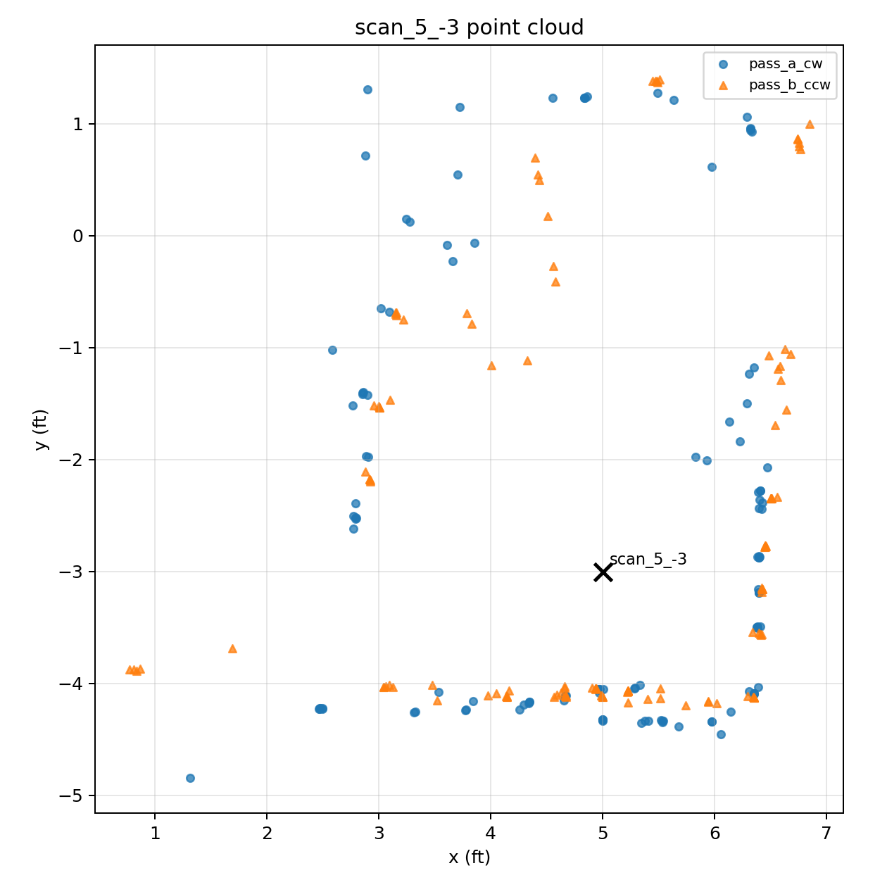
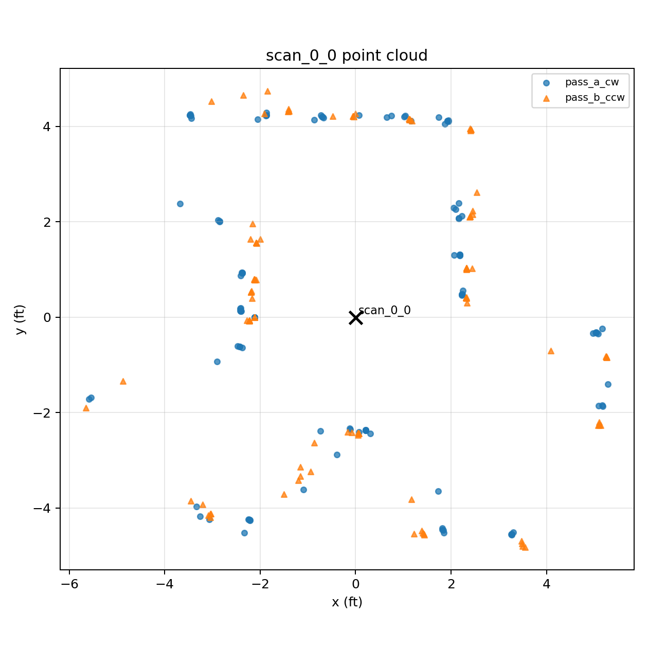
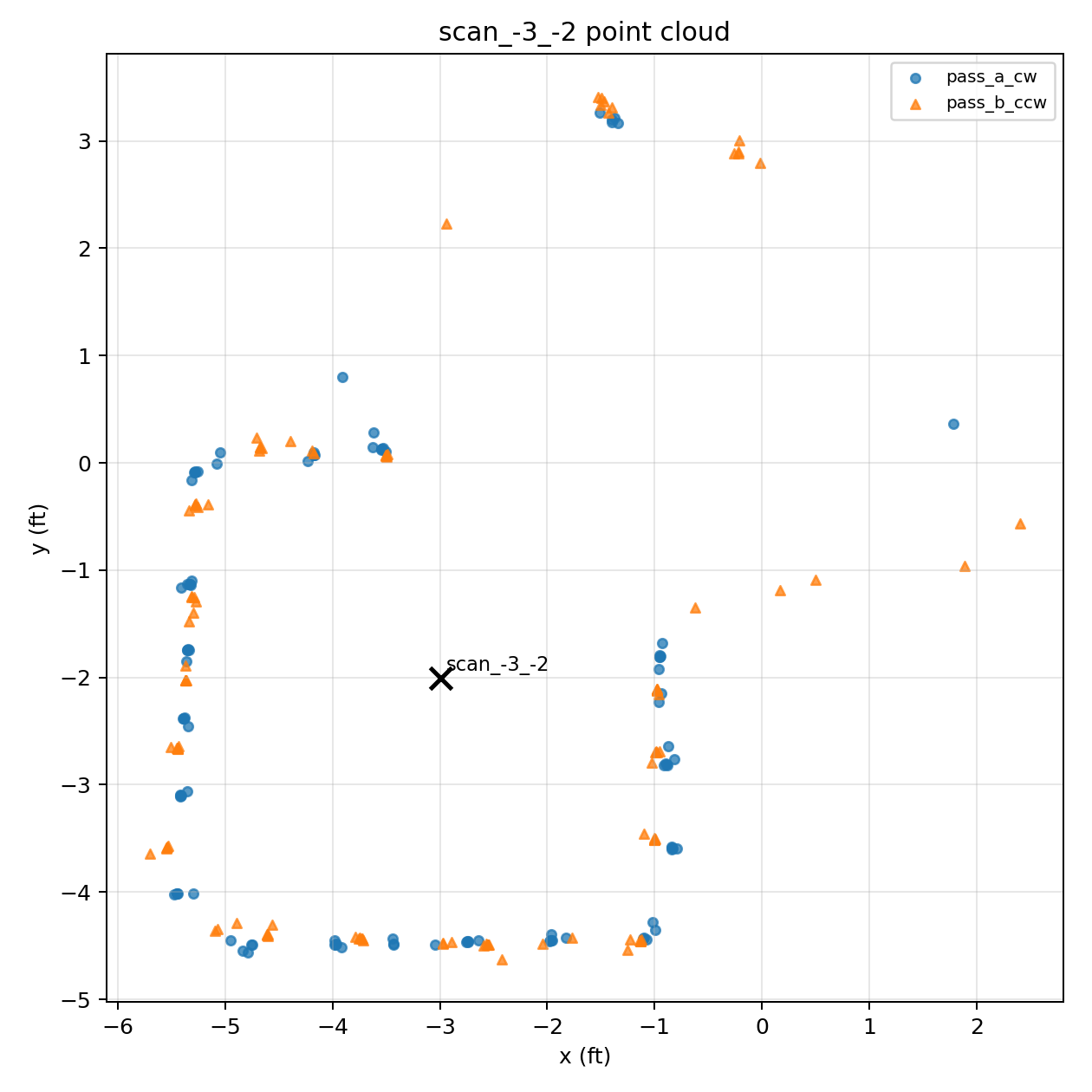
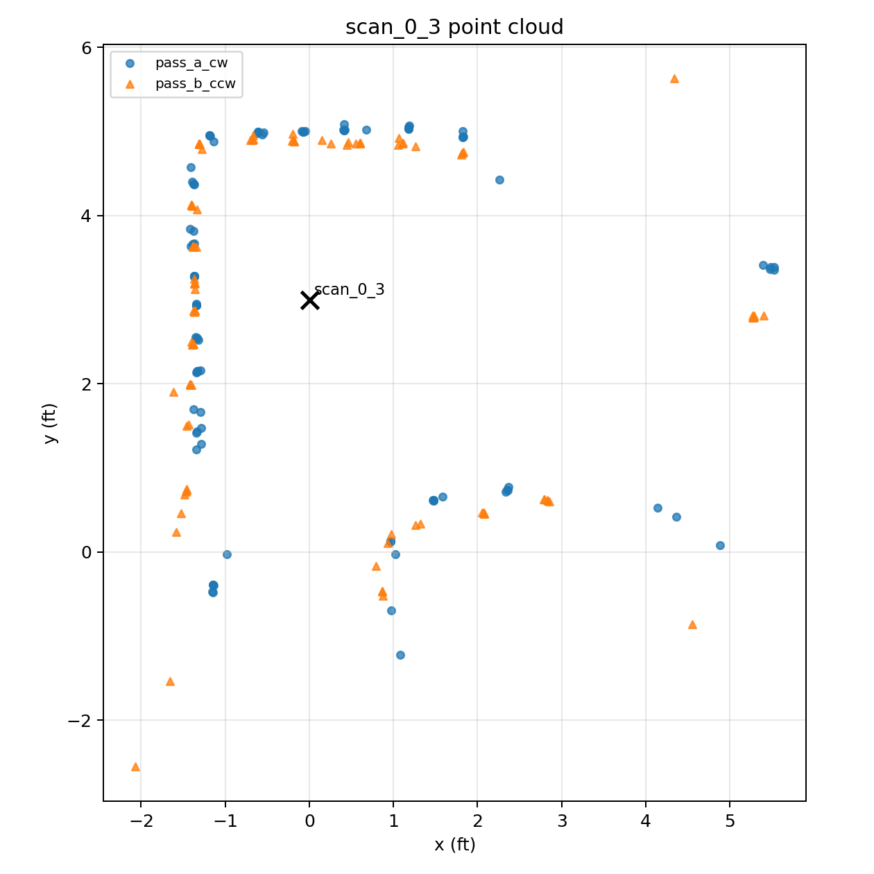
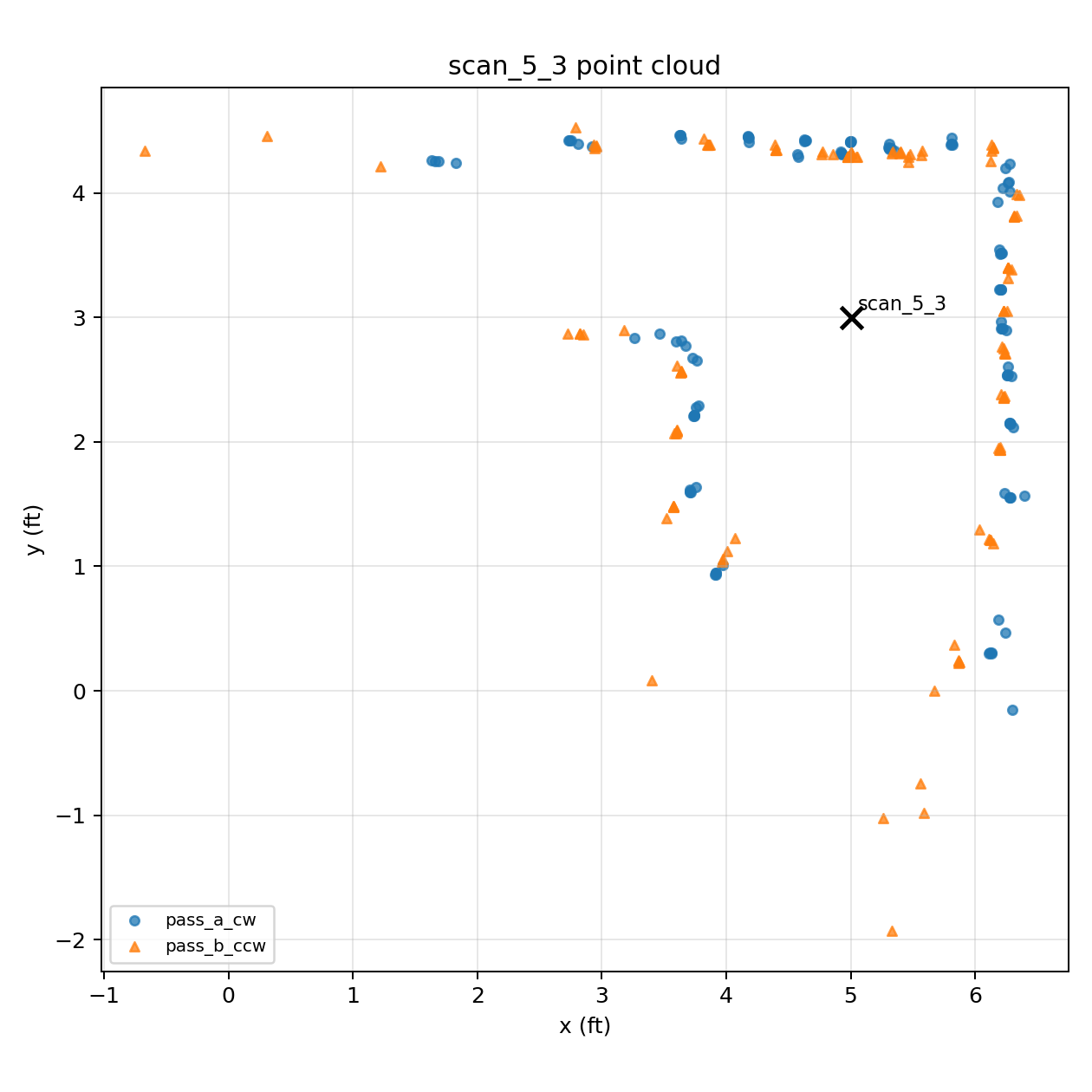
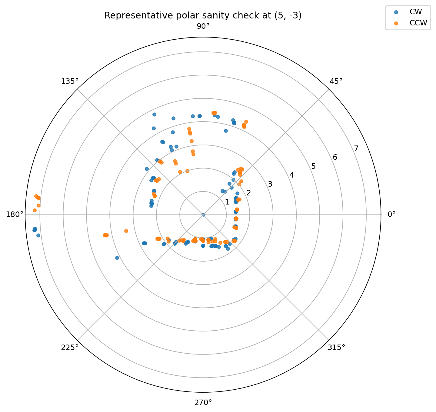
The single scan plots were my sanity check before merging.
Merged Map
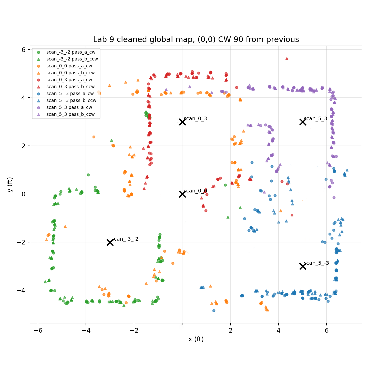
I merged all scans into the room frame with rigid transforms only. Then I cleaned the cloud with two simple filters: a distance range filter from 0.15 ft to 12 ft, and a per scan radius filter that kept only points within 6 ft of the scan origin. This removed most of the far grazing angle returns without deleting the useful nearby walls.
Python: map cleanup after room frame transform
def cleanup_map_points(points_room, scan_poses,
                       min_range_ft=0.15, max_range_ft=12.0, max_scan_radius_ft=6.0):
    df = points_room.copy()

    # Remove obviously bad ranges from the merged cloud.
    df = df[(df['range_ft'] >= min_range_ft) & (df['range_ft'] <= max_range_ft)].copy()

    # Remove far hits that are too far from the scan origin.
    keep_rows = []
    for scan_key, g in df.groupby('scan_key'):
        pose = scan_poses[scan_key]
        dx = g['x_ft'] - pose['x_ft']
        dy = g['y_ft'] - pose['y_ft']
        keep_rows.append(g[np.sqrt(dx**2 + dy**2) <= max_scan_radius_ft])

    return pd.concat(keep_rows, ignore_index=True)


points_clean = cleanup_map_points(points_room, scan_poses)
This cleanup was done after transforming all hits into the room frame. The first filter removed impossible or very short readings, and the second filter removed distant grazing angle returns that tended to distort the walls.
The raw merged cloud is shown below. It contains all 1270 valid measurements from the 10 runs.
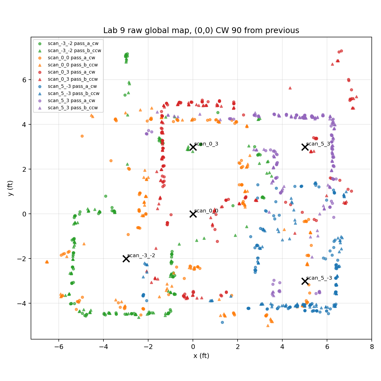
After cleanup, 1092 points remained. This version is much easier to fit with line segments.
Line Map And Discussion
I manually fit line segments to the cleaned point cloud and exported the line endpoints for the next lab. In the plot below, the black line segments are the walls and obstacles estimated from the point cloud, and the green line segments are the actual room boundaries and obstacles.
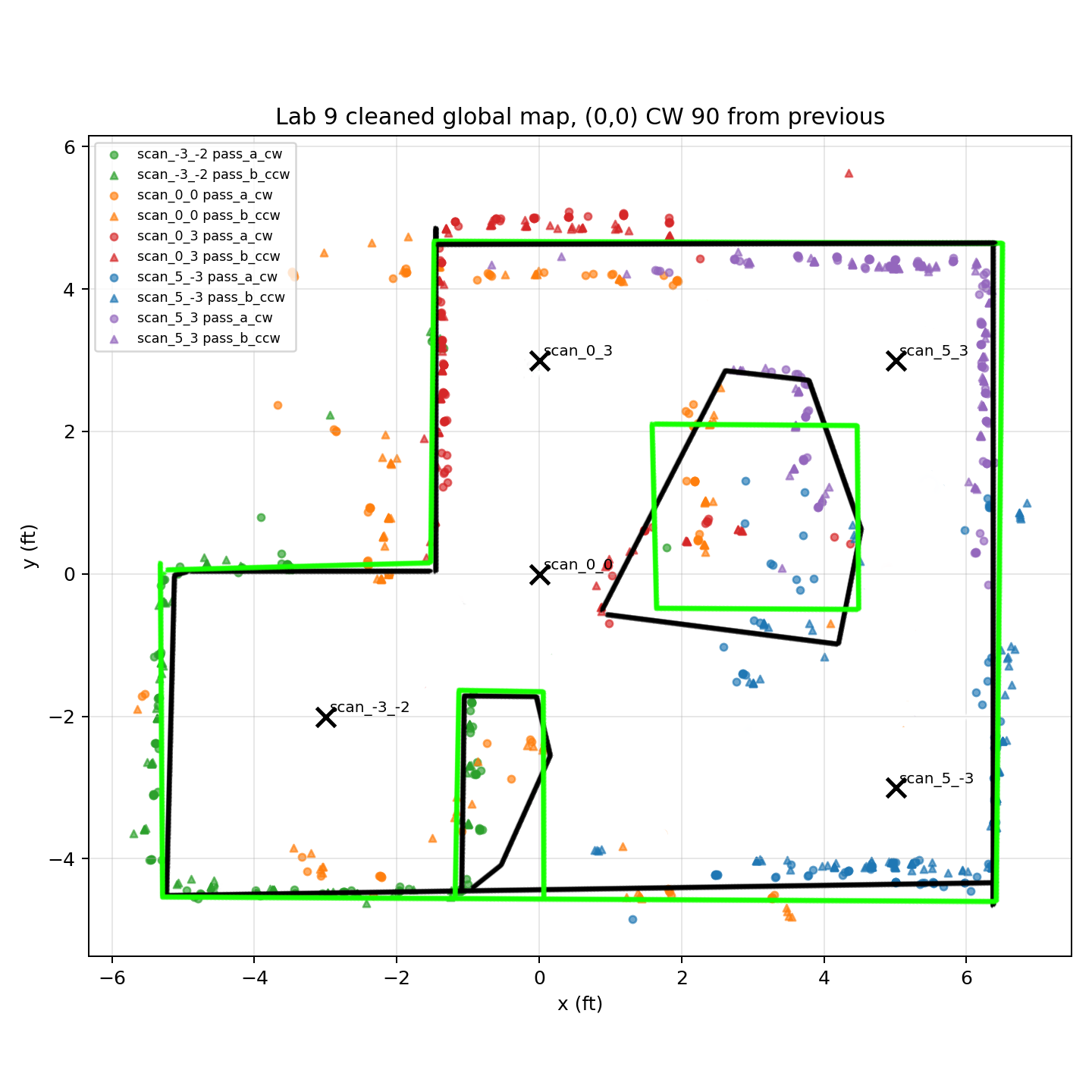
The outside walls came out very well because they were seen from several locations and at better angles. The clockwise and counterclockwise passes also overlapped closely on those walls, which gave me confidence that repeatability was good enough for merging. The middle wall segments and obstacles are less accurate. The main failure mode is that the point cloud usually makes obstacles look a little larger than they really are. That is acceptable for path planning because it is conservative. The robot may choose a slightly longer path, but it is less likely to collide. The remaining error mainly comes from heading error, placement error between marks, and ToF bias at oblique angles.
Meet my cat Mulberry! 🐱